Introduction
As pointed out in Chapter 1, GENTRA uses Lagrangian equations for the representation of the particulate phase. These equations are listed in the present chapter, in which some details of the integration procedure are also given.
It should be pointed out that users do not need to be acquainted with the contents of this chapter to be able to operate GENTRA successfully; the chapter is therefore provided as a reference for users who need to be concerned with the mathematical basis of GENTRA.
The continuous-phase equations
GENTRA uses, for the description of the continuous phase, the Eulerian equations built in PHOENICS for single-phase flows, which have the general form:
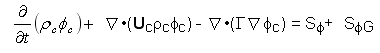 [6.1]
[6.1]
where
fc is the continuous-phase property modelled;
rc is the continuous-phase density;
Uc is the continuous-phase velocity;
G is an exchange coefficient for fc;
Sf are the sources/sinks of fc; and
SfG are the interphase sources computed by GENTRA and accounting for the transfer of fc between the phases.
Equations such as equation (6.1) are set up by PHOENICS following the instructions supplied by the user through the PHOENICS Input Language or a PHOENICS menu.
The variables fc for which GENTRA will expect PHOENICS to solve equations like equation (6.1) vary from problem to problem, as follows:
(a) For all particle types, except for stubborn particles, GENTRA requires the velocity component in each of the co-ordinate directions considered (U1/V1/W1)
(b) For particles with heat transfer, melting/solidifying particles and vaporising droplets, an equation for enthalpy H1, or temperature, TEM1, is also required.
(c) For vaporising droplets, the mass-transfer term (SfG in equation 6.1) is inserted into the equation for P1 (which in PHOENICS is the continuity/pressure correction equation); and a transport equation must also be set up for VAPO, the mass fraction of droplet vapour in the continuous phase.
(d) When the stochastic turbulence model is used, the equations for KE (turbulence kinetic energy) and EP (its rate of dissipation) must also be solved.
The solution of the above variables can be replaced by the simple storage (without solution) of their values when GENTRA is to track the particles through a "frozen" flow-field.
Lagrangian equations
In the simulation of particle behaviour, Lagrangian equations are solved which describe the evolution of the position, velocity (momentum), mass and temperature (enthalpy) of the particle. Some combination of these equations is employed for the different types of particle available within GENTRA as detailed in Section 2.5. In the following sub-sections, descriptions are presented of each of the Lagrangian equations, and their relevance to each of the particle types is discussed. The method of integration of these equations is explained in Section 6.5.
- The particle position equation
- Lazy particles. For lazy particles it is assumed that the particle velocity is identical to the instantaneous continuous-phase velocity:
- Stubborn particles . For stubborn particles, the particle velocity is constant and equal to the value prescribed at the inlet.
- The particle momentum equation
- The particle mass equation
- The particle enthalpy equation
The evolution of the particle position is determined from solution of the following equation:
dxp/dt= Up [6.2]
where vector xp is the particle position; and Up is the particle velocity. Generally, the particle velocity is determined from solution of the particle momentum equation, as described in Section 6.3.2. However, for lazy and stubborn particles, the particle velocity is calculated as follows:
Up = Uc +Uc'
where: Uc is the time-averaged continuous-phase velocity; and Uc' is a turbulent velocity fluctuation calculated from the local turbulence conditions when the stochastic turbulence model is activated.
Up = constant
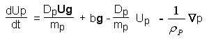
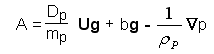
The velocity of the particle, Up, is computed from the particle momentum equation:
![]() [6.3]
[6.3]
where
mp is the mass of the particle;
Dp is a drag function, to be defined below;
U is the continuous-phase instantaneous velocity, U = Uc + U'c. Uc is the continuous-phase average velocity, and U'c is a turbulent fluctuation which is added if the stochastic turbulence-model is active (see Section 6.4.1);
g is the gravitational acceleration;
b is a buoyancy factor, equal to (1- ) if the buoyancy option is active or to 1.0 otherwise;
Vp is the particle volume; and
�
p is the continuous-phase pressure gradient.The first term on the right-hand side of equation (6.3) represents the drag force exerted by the continuous phase on the particle; and the second represents the gravitational force. Source terms accounting for the virtual mass and Basset forces, Saffman lift and Magnus forces are neglected. The conditions under which these source terms can be neglected have been given by Faeth (1983).
The drag function Dp used in GENTRA has the following form:
Dp = 0.5 r Ap CD |U - Up| [6.4]
where
Ap is the particle projected area, pDp2/4 [6.5]
CD is the drag coefficient, which by default is given by
![]() [6.6]
[6.6]
where Re is the particle Reynolds number.
(This correlation, provided by Clift, Grace and Weber (1978), is valid for rigid spherical particles and Re<3x10⁵)
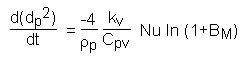
The evolution of the mass of the particle, mp, is described by the particle mass equation, thus:
![]() [6.7]
[6.7]
where:
dp is the diameter of the particle;
kv is the thermal conductivity of the vapour produced by the evaporation of the droplet;
cpv is the specific heat capacity of that vapour;
Nu is the Nusselt number, determined from the following correlation:
Nu = 2(1 + 0.3 Re0.5 Pr0.33) F [6.8]
where: Pr is the laminar Prandtl number for the continuous phase; and
F is the Frossling correction for mass transfer, given by:
F = 1/BM ln (1 + BM) [6.9]
BM is the mass transfer number, which represents the "driving force" in the mass transfer process, and is defined by:
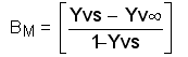 [6.10]
where:
Yvs is the mass fraction of vapour at the surface of the droplet; and
Yv� is the mass fraction of vapour in the gas surrounding the droplet.
The mass fraction of vapour at the surface of the droplet is calculated thus:
![]() [6.11]
[6.11]
where:
P is the total pressure of the fluid surrounding the droplet;
Pvs is the partial pressure of the vapour at the surface of the droplet at the saturation conditions defined by the droplet temperature;
Wc is the molecular weight of the surrounding fluid; and
Wv is the molecular weight of the vapour.
Within GENTRA, the mass transfer equation is employed only in the simulation of vaporising droplets.
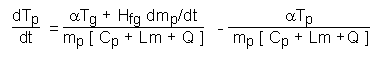
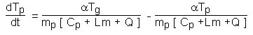
The temperature of the particle, Tp, is determined from solution of the particle enthalpy equation. In its most general form, the particle enthalpy equation may be written:
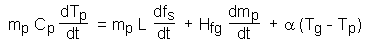 [6.12]
where:
Cp is the specific heat capacity of the particle;
L is the latent heat of solidification;
Hfg is the latent heat of evaporation;
fs is the proportion of the solid phase in the particle (the solid fraction);
a
is the heat transfer coefficient between the particle and the surrounding fluid; andTg is the temperature of the surrounding fluid.
The specific heat capacity of the particle may be a function of both the temperature and the composition of the particle, thus:
Cp = fs (Cps (Tp)) + (1 - fs) (Cpl (Tp)) [6.13]
where Cps and Cpl represent the specific heats of the solid and liquid phases of the particle as functions of the particle temperature.
The latent heat of solidification of the particle is defined as the difference in total enthalpy of the solid and liquid phases at a given temperature:
![]() [6.14]
[6.14]
where:
hso is the enthalpy of the solid phase at the reference temperature of 0.0 K; and
hlo is the enthalpy of the liquid phase at the same reference temperature.
In the case of the specific heat capacities of the two phases being equal, the latent heat of solidification is independent of temperature and equal to hlo - hso.
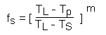
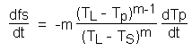
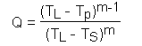
The solid fraction of the particle is determined from the following equation:
![]() [6.15]
[6.15]
where:
TS is the solidus temperature of the particle;
TL is the liquidus temperature of the particle; and
m is the solidification index.
The particle heat transfer coefficient, a, is determined from:
a
= p kc Nu dp [6.16]where kc is the thermal conductivity of the continuous phase.
The particle enthalpy equation is not used in the simulation of lazy, stubborn or isothermal particles. For the other particle types, it is employed in the following reduced forms:
Heat exchanging particles:
[6.17]
in which the terms representing solidification/melting and evaporation are absent.
Melting/solidifying particles:
[6.18]
in which the term representing evaporation is not present.
Vaporising droplets:
[6.19]
in which the solidification term is absent.
Submodels
- Stochastic turbulence model
- Rotating-coordinate systems
GENTRA features an optional stochastic turbulence model (Gosman and Ioannides, 1981) which accounts for the effects on particle dispersion of the turbulent fluctuations of the continuous-phase velocity.
The model uses, as the continuous-phase velocity in the drag force term of the momentum equation (equation (6.3)), a sum of the average velocity Uc and a "fluctuating" component U'c:
U = Uc + U'c [6.20]
where:
Uc, the average velocity, is obtained from the Eulerian equations for the continuous phase; and
U'c, the fluctuating component, is calculated assuming that each component follows a normal distribution with a mean value of 0.0 and a standard deviation of
![]() [6.21]
[6.21]
where K is the turbulence kinetic-energy.
The fluctuating component U'c is assumed to act over a time interval Dts which is the minimum of:-
(a) Dte, the lifetime of the local eddy which the particle is assumed to be traversing; and
(b) Dtr, the transit time taken for the particle to cross the eddy.
The eddy lifetime Dte is computed as:
![]() [6.22]
[6.22]
where le is the eddy size:
![]() [6.23]
[6.23]
where: e is the rate of dissipation of turbulence kinetic energy, and C� is a constant in the turbulence model.
The particle transit-time Dtr is given by
![]() [6.24]
[6.24]
In rotating-coordinate systems, the particle (Up) and continuous-phase (Uc) velocities solved for by GENTRA and PHOENICS are the ones relative to the rotating system. Coriolis and centrifugal sources must therefore be included in the momentum equations.
For the particle, the extra term in the momentum equation (equation (6.3)) is:
![]() [6.25]
[6.25]
where:
![]() is the angular speed of rotation (expressed here
as a vector along the axis of rotation);
is the angular speed of rotation (expressed here
as a vector along the axis of rotation);
xp is the particle-position vector; and
![]() indicates cross product.
indicates cross product.
The rotating-co-ordinate feature of GENTRA is activated automatically when its PHOENICS counterpart is activated. See the entry ROTA in the SATELLITE help dictionary for details on how to activate it and how to specify the axis of rotation and the angular speed.
(Note that the FORTRAN logical variable ROTCOO can be used to deactivate the automatic introduction of this feature. See Appendix C for details).
The numerical integration of the particle equations takes place according to the following sequence:-
(a) The Lagrangian time-step is calculated;
(b) The particle is moved;
(c) The particle properties at the new position are calculated;
(d) The interphase sources are calculated.
These four steps are dealt with in subsequent subsections.
- Calculation of the Lagrangian time-step ?tl
- Moving the particle
- Integration of momentum, mass and enthalpy equation
- Calculation of sources
The Lagrangian time-step is computed by GENTRA as:-
Dtl = max (t0,min (t1,t2,t3)) [6.26]
where t0 to t3 are as follows:
(a) t0 is a minimum time-step size, given by the FORTRAN variable GDTMIN. Its default value is 10.0-7; users can re-set it in Group 1 of GENIUS.
(b) t1 is the minimum cell-crossing time divided by the Q1-set variable GLAGTS (the minimum number of Lagrangian time-steps per cell specified by the user). The minimum cell-crossing time is estimated by GENTRA for each cell using the minimum cell dimension and the maximum velocity component.
(c) t2 is the momentum relaxation time.
If the particle momentum equation is re-written as
![]() [6.27]
[6.27]
t2 is calculated as , where a is a multiplication factor.
a is available (through GENIUS) as the FORTRAN variable GRTFRL. Its default value of 1010 effectively excludes t2 as a criterion in equation (6.26) (since it is larger than the others).
Users wanting to relate the time-step Dtl to the momentum relaxation-time t2 can reset GRTFRC in Group 1 of GENIUS. However, this might result in very small time-steps for small particles.
(d) t3 is the user-supplied maximum time-step size (PIL variable GDTMAX).
Note that the time step thus computed may be further reduced by GENTRA after the integration of the position equations as follows:
(a) The particle is not allowed to jump, in the current time-step, beyond the neighbouring cells;
(b) for boundary cells (i.e., cells at the boundaries of the computational domain or cells next to internal blockages), a particle crossing the cell boundary is placed on the cell boundary by reducing the time-step.
After computing the time-step ?tl, the particle is "moved" by integrating the particle-position equations. The particle-position equation (equation (6.2))
dxp/dt= Up
is integrated as:
xnp = xop + Uop Dt [6.28]
where:
n denotes the value at the end of the time step; and
o denotes the value at the beginning of the time-step.
GENTRA integrates the position equations in the GENTRA Cartesian System; in cylindrical-polar grids, equation (6.28) can optionally be integrated in polar co-ordinates (i.e., using the radius, the angle and the circumferential and radial velocities as variables). The FORTRAN logical variable POLTRC (see Appendix C), accessible from GENIUS, controls this option. (Note, however, that, in order to avoid the singularity at the polar axis y=0, GENTRA will always track in Cartesian co-ordinates in the centre of the grid (IY=1).)
The equations representing the momentum, mass and enthalpy of the particles can be represented in the following generalized form.
dx/dt = A - Bx [6.29]
where x represents the variable to be solved (i.e. momentum, mass or enthalpy), and A and B are constants.
The equation is integrated over the Lagrangian time step ?tl such that the value at the end of the time step, xn, can be expressed in terms of the value at the start of the time step, xo, and the constants A and B, thus:
![]() [6.30]
[6.30]
If the constant, B, in equation (6.29) is zero, implying that the rate of change of x is independent of the value of x, the use of equation (6.30) would result in division by zero. Hence, in this case, equation (6.29) is integrated thus:
x
n = xo + ADt [6.31]The form of the constants in equation (6.29) is dependent on the equation being solved. In the following subsections, the method of integration for each of the particle equations will be presented.
The particle momentum equation
The particle momentum equation (equation (6.3)), may be expressed in the form of equation (6.29) as:
 [6.32]
from which the constants A and B of equation (6.29) can be seen to be:
 [6.33a]
![]() [6.33b]
[6.33b]
The particle mass equation
For the case of a particle evaporating in a constant environment, and at constant temperature, the rate of change of particle surface area with time is constant. This is taken into account in the method employed for the integration of the particle mass equation, which is cast into the form of an equation for the rate of change of particle surface area (dp2), thus:
 [6.34]
This is integrable using equation (6.31), in which the constant, A, is equal to the right hand side of equation (6.34):
![]() [6.35]
[6.35]
The rate of change of particle mass is then deduced from the change in particle diameter.
The particle enthalpy equation
The particle enthalpy equation its most general form is given by equation (6.12), thus:
![]()
Before integrating this, the solidification/melting term is expressed in a more useful form by noting the relation between the solid fraction, fs, and the particle temperature, tp, equation (6.15):
This can be differentiated with respect to the particle temperature, yielding:
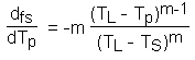 [6.36]
and the original term representing the rate of change of solid fraction with time can be expressed as:
This may be substituted into the general particle enthalpy equation, which may be written in the form of the general particle equation (equation (6.29)):
 [6.37]
where:
 [6.38]
This may then be integrated via equation (6.30).
For the three types of particles involving heat exchange which are available in the current version of GENTRA (ie heat exchanging, melting/solidifying and vaporizing), some terms of the general enthalpy equation are absent. For each of these particle types, there now follows the form of equation (6.37) which is employed.
Heat exchanging particles:
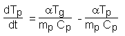 [6.39]
Melting/solidifying particles:
 [6.40]
Vaporising droplets:
![]()
![]() [6.41]
[6.41]
As the particles traverse each cell, exchange of mass, momentum and enthalpy may occur. For example, a particle which is travelling faster than the surrounding fluid will be decelerated and will transfer momentum to that fluid. The sources which must be added to the continuous-phase transport equations to represent these transfers are as follows.
Mass transfer
![]() [6.42]
[6.42]
where:
n denotes values at the end of the Lagrangian time step;
o denotes values at the start of the Lagrangian time step;
h
is the number flowrate of particles for that parcel (ie the mass flowrate of that parcel divided by the mass of an individual particle); andS
is the summation over all of the Lagrangian time steps required for the particle to traverse the cell, and for all particles.The mass added to the continuous-phase continuity equation represents fluid evaporated from the droplet surfaces. A PHOENICS transport equation (such as equation (6.1)) is solved for the vapour mass fraction, and sources must also be added to this equation to account for the vapour added from the particles. The source in the vapour mass fraction equation is identical to that added to the continuity equation.
Momentum transfer
The source of momentum, Smom, which appears in the continuous-phase momentum equations is equal to the rate of change of particle momentum as each particle parcel traverses a cell:
![]() [6.43]
[6.43]
where Vp is the particle velocity integrated from the momentum equation without body forces.
Enthalpy transfer
The source of enthalpy, Sh, which appears in the continuous-phase
enthalpy or temperature equation is:![]() [6.44]
[6.44]
where hp is the enthalpy of the particle relative to a value of zero at 0.0 K.
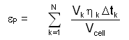 [6.47]
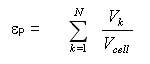 [6.48]
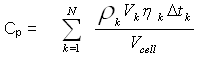 [6.49]
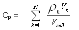 [6.50]
 [6.52]