Encyclopaedia Index
Contents
- Macros in general
- Macros for PHOTON, Autoplot and WinPHOTON
- Macros for the Satellite
- Macros for the VR-Viewer
a. Macros in general
'Macro' is the name given to a file which contains a succession of
commands which are understood, and obeyed, by executable programs.
Their chief functions are:
- to relieve program users of the tedium of frequently repeating
the same set of key-strokes;
- permitting some operations to be performed automatically, which
would otherwise require user intervention.
In the PHOENICS suite of programs, macros are used in conjunction
with:
- PHOTON and Autoplot
- Satellite
- VR-Viewer.
Macros are most-often created by a knowledgable person with the aid
of a text editor; however both PHOTON and the Viewer possess some
capabilities of creeating macros by recording the action taken by
a human user during an interactive session.
b. Macros for PHOTON, Autoplot and WinPHOTON
The first macros introduced into the PHOENICS suite were for the
PHOTON results-display module. They were called 'USE files', because
the command activating them was:
USE file-name
where file-name was the name of the macro containing the commands.
Often the file name was simply 'u' or 'U'; and indeed both PHOTON and
Autoplot, as their first actions, look for a file with such a name in
the local directory, and, if they find one, proceed to execute the
commands which they maintain.
With the development of the PHOENICS Input-File Library, it has become
convenient
to include the relevant macro in the Q1 file itself, from which it is
also copied into the q1ear; then the only instruction needed in the
the 'u' file is:
use q1
or
use q1ear
If the 'PHOTON USE macro' box is ticked, and preferably some others,
such as 'NX=1' and 'time-dependence' so as to prevent many hundreds of
cases being found, a window containing a list of cases will appear,
of which the top ones might be:
The cases listed below (if any)
 possess the following features:

 dim NX = 1
 dim Time-dependence
 ppp PHOTON USE macro
 case 322 Laminar Flow In Pipe-Transient
 ___ has PHOTON USE macro for displaying results
 ___ has DISPLAY...ENDDIS description of case
 ___ time-dependent
 ___ cylindrical grid
 ___ NX = 1
 ___ computes heat transfer
 case 323 Central Obstacle In Laminar Pipe
 ___ has PHOTON USE macro for displaying results
 ___ has DISPLAY...ENDDIS description of case
 ___ time-dependent
 ___ cylindrical grid
 ___ NX = 1
 ___ computes heat transfer
 case 334 Spherical Blast Wave
 ___ has PHOTON USE macro for displaying results
 ___ has DISPLAY...ENDDIS description of case
 ___ time-dependent
 ___ cartesian grid
 ___ NX = 1
 ___ NZ = 1
 ___ uses isentropic-gas law for density
 ___ fiinit(prps) = -1, so use PIL properties for domain fluid
To take the last-mentioned case as an example, case 334, the relevant
macro can be seen by clicking
here.
The PHOTON macro here starts on the line below PHOTON USE
and ends on the line above ENDUSE.
A similarly-conducted search for library cases containing AUTOPLOT USE
macros might yield a list starting as follows:
The cases listed below (if any)
 possess the following features:

 dim Time-dependence
 aaa AUTOPLOT USE macro
 case p112 Trans. phase separation of gas/liq:P112
 ___ has AUTOPLOT USE macro for displaying results
 ___ has DISPLAY...ENDDIS description of case
 ___ time-dependent
 ___ cartesian grid
 ___ NY = 1
 ___ NZ = 1
 ___ involves buoyancy
 case c203 CHEMKIN - 0D-Transient Reaction
 ___ has AUTOPLOT USE macro for displaying results
 ___ has DISPLAY...ENDDIS description of case
 ___ time-dependent
 ___ cartesian grid
 ___ NX = 1
 ___ NY = 1
 ___ NZ = 1
 ___ computes heat transfer
 ___ uses CHEMKIN option for density
The AUTOPLOT macro here starts on the line below AUTOPLOT USE
and ends on the line above ENDUSE.
WinPHOTON, which is a Windows-based version of the older PHOTON
(which now contains AUTOPLOT) can handle most PHOTON USE macros, but is
currrently (October 2005) less satisfactory with AUTOPLOT USE files.
This deficiency will be remedied.
c. Macros for the Satelllite
Many macros provided by CHAM for the Satellite take the form of library
cases. Examples are:
- Core-library case 050, which consists of the lines:
mesg(unigrid macro has been loaded  ! prints message on screen
grdpwr(t,lstep,tlast, 1.0)          ! sets uniform time intervals
grdpwr(x,nx   ,xulast,1.0)          ! sets uniform x intervals
grdpwr(y,ny   ,yvlast,1.0)          ! sets uniform y intervals
if(parab) then                      ! sets iniform z intervals
 parab                              !   but differently for
 zfrac(1)= -nz;zfrac(2)=1/nz        !   parabolic and non-parabolic
else                                !   cases
 grdpwr(z,nz   ,zwlast,1.0)
endif
if(cartes) then                     ! prints message on screen
 mesg(uniform cartesian grid        !   but differently for
else                                !   cartes=t and cartes=f
 mesg(uniform polar grid
endif
This macro is used by inserting in the Q1 file the line:
#$050
or,
since the character variable unigrid has been set equal
to
$050
by the always-loaded-first library case
014,
which is itself a macro,
by inserting
#unigrid.
The following few lines from library case 100 illustrate this:
REAL(XLENGTH,YLENGTH,ZLENGTH)
XLENGTH=1.0;YLENGTH=1.0;ZLENGTH=1.0

  domain size and grid
NX=10; NY=10; NZ=10; xulast=xlength; yvlast=ylength; zwlast=zlength

#unigrid
wherein it should be noted that NX, NY, etc were set before the
loading of unigrid, whereas TLAST and LSTEP were left at their
default values, because the case was not time-dependent.
- Case 493 is
a macro which contains settings which are useful for setting up radiation
simulations.
- The comments at the top of macro 493 are worth reading because
they refer to another way of introducing a macro into a Q1 file, namely
by placing the commands in a file and then using the PIL command
intrpt.
Thus, inserting in the Q1 the line:
intrpt(r,\phoenics\d_earth\d_core\inplib\050.htm)
would have precisely the same effect as the use of #unigrid;
and any file can be imported in this way, whether it is a
macro or not.
- Finally, it may be interest to observe that almost all of the
actions initiated by a user of Satellite's interactive data-input menu
are brought about by activation of an appropriate macro.
An example is the following:
008: set default turbulence constants
cmu=0.5478; cd=0.1643; c1e=1.44; c2e=1.92
case ienuta of
+ when 1
+   cmu=0.0845**0.25; cd=0.0845**0.75; c1e=1.42; c2e=1.68
+ when 2
+   c1e=1.15; c2e=1.9
+ when 4
+   c1e=1.15; c2e=1.9
+ when 7
+  gc3e=0.21; c1e=1.24; c2e=1.84; gct1=0.29; gct3=1.166
+ when 10
+  c1e=5./9.; c2e=0.075
+ when 11
+  c1e=5./9.; c2e=0.075
endcase
which is one of many to be found in the files residing in
the directory
\phoenics\d_satell\d_men\cormenn\menu .
The SATELLITE's macro facility is thus of very great use to
those users of PHOENICS who prefer sometimes to write
a Q1 directly, rather than having it written
for them by the VR-Editor.
d. Macros for the VR-Viewer
Contents
- The function of a VR-Viewer macro
- How to create a macro
- Running a macro
1. The function of a VRV macro
A typical use of a VRV macro is to record a particular view and
magnification, and then restore it whenever required, for example when
replaying the macro commands included in a Q1 file for the graphical display
of the results.
Using a macro in this way will guarantee that a sequence
of images from different phi files, perhaps generated on separate occasions,
can all use the identical view and magnification settings.
A macro file can contain a single image, or a sequence of images separated by PAUSE commands.
Macro command files are ASCII text files, and can be edited (or created)
by hand using any convenient text-file editor.
2. How to create a macro
Macro files can be created by using the VR-Viewer macro facility or by
hand-editing using any text editor as follows
- Press the MACRO button
 on the Hand set. This will bring up the MACRO Functions dialog.
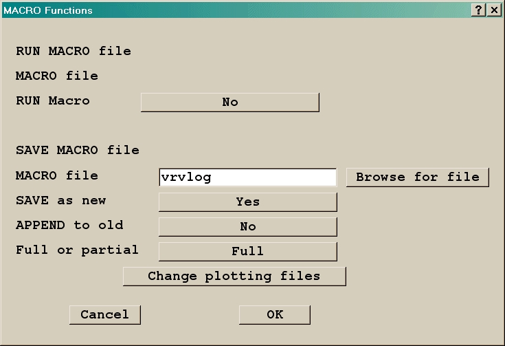
- Select 'Save as new - Yes', enter a filename then click OK. The current
view settings will be written to the selected file.
The default filename is vrvlog.
IMAGE: MACRO Functions dialog (save)
Partial will save a short form of the macro, with only non-default settings and
changes from frame to frame. This form is suitable for inclusion in the Q1 embedded between
VRV USE
and
ENDUSE
Full will save all settings for each frame, resulting
in a longer macro, but guaranteeing that the images will be reproduce exactly regardless
of starting point.
- Pressing F4 or clicking the F4 icon will overwrite the currently-selected
'Save-as-new' file.
- Press the MACRO button on the Hand set. Select 'Append to old - Yes'
then click OK. The current view settings will be added to the end of the
selected file. Individual views will be separated by a PAUSE command.
- Pressing F5 or clicking the F5 icon will add to the currently-selected
'Append' file. Individual views will be separated by a PAUSE commands
- Hand-editing a file with any text editor
The macro files created by the VR-Viewer function can be very lengthy,
especially if the macro is to be included in a Q1 input file; in that case
many of commands can be removed by hand-editing. The following two macro
files will produce the same images.
The Macro saved by the VR-Viewer
macro function
The above macro after
hand-editing
As seen, only those commands that change a default or change an
existing setting need be placed in the macro file.
The following are simple rules for hand-editing:
Once you are getting familiar with the commands, you may create macros
without VR-Viewer in the same way as for PHOTON USE commands.
A complete list of valid VR-Viewer macro commands is given in Appendix VR-Viewer Macro Commands below.
VR-Viewer can also read a limited range of commands in the PHOTON command language. This enables it
to display images from PHOTON USE files, which may be embedded in the Q1. Those compatible PHOTON commands
are also listed at the end of the Appendix.
However, if you need to change the default settings or draw streamlines, it is recommended to use the VR-Viewer
macro function to save the macro commands first into vrvlog and then reduce its size by hand-editing before
adding it to a Q1 file.
3. Running a macro
The macro commands can be copied into the Q1 input file, by placing
them between the statements VRV USE and ENDUSE. These two lines, and all
the macro lines, must start in column 3 or more to ensure that they are
treated as comments by the VR-Editor.
Macros can be run as follows:
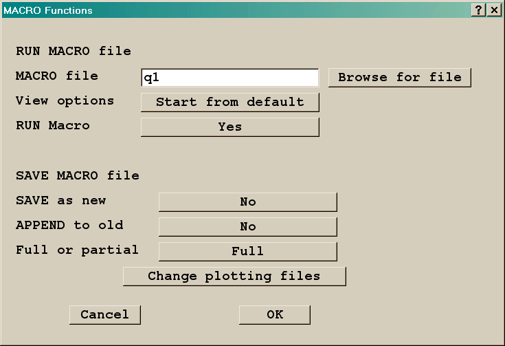
- Press the MACRO button on the Hand set, then 'Run Macro'. Click Ok
and the selected file will be read, and any macro commands in it will
be executed.
IMAGE: MACRO
Functions dialog (run)
The default file name is Q1.
- For each image, there will be a text message window. Click 'Ok' to continue or 'Cancel' to
stop the macro.
- Pressing F3 or clicking the F3 icon will run the currently-selected
macro file.
Appendix VR-Viewer Macro Commands
The commands set the state of the VR-Viewer settings. The screen image
is updated when a PAUSE command is encountered, or the end of the file is
reached. The image is the outcome of the final states of all the settings.
The commands making up the macro language can be divided into a number
of groups. Only those commands that change a default or change an existing
setting need be placed in the macro file.
The individual commands can be shortened, as long as the remaining part
is unique.
Setting the File Name
FILE name [xyz name for BFC case] Sets the name of the PHI (and XYZ file)
to plot
FILE + Read the next saved PHI file (equivalent to F8)
FILE - Read the previous saved PHI file (equivalent to F7)
USE file Read commands from another file. Use files can be nested
to a depth of 5.
Setting the View
VIEW x, y, x Sets the View direction
UP x, y, z Sets the Up direction
VIEW CENTRE x, y, z Sets the Cartesian co-ordinates of the
view centre - the point about which the image rotates.
[VIEW DEPTH depth For the Windows Viewer, sets the View Depth.
The default is 3.0. A value of 100000 makes the view isometric]
[VIEW TILT angle For the DOS/Unix Viewer, sets the perspective
angle. The default is 0.8. A value of 0.0 makes the view isometric]
SCALE scalex, scaley, scalez Sets the overall domain scaling
factors
The View Centre, Scale factors and View Depth/Tilt settings can be
seen by clicking on '
Reset
'.
Setting the Position of Screen Items.
The primary keyword POSITION is followed by a secondary keyword to
identify which item is under consideration. The two integers represent
the normalised location in the range 0.0 - 1.0 for the first character
of the item. [Origin is at the top left hand corner of the client area.]
POSITION CELL x, y
POSITION CONTOURKEY x, y
POSITION TITLE x, y
POSITION PROBE x, y
Setting the Variable to be Plotted
VARIABLE name Sets the name of the current plotting variable
VARIABLE RANGE min max Sets the minimum and maximum values
for the plot.
If the minimum/maximum values are changed from the default (i.e.
the current field values), the set values will be used for all subsequent
plots for this variable. Setting specific minimum and maximum values
ensures that contour plots from different PHI files are scaled consistently.
Controlling the Plot Elements
Contours
CONTOUR ON / OFF / CLEAR Clear also deletes all saved slices.
CONTOUR SCALE ON / OFF Controls the display of the contour
scale.
CONTOUR OPAQUENESS iopaq Sets the contour opaqueness to iopaq.
CONTOUR BLANK ON / OFF Sets the out-of-range transparency.
CONTOUR AVERAGE ON / OFF Sets contour averaging on or off.
Vectors
VECTOR ON / OFF / CLEAR Clear also deletes all saved slices.
VECTOR SCALE vscal Sets the vector scaling factor
VECTOR REFERENCE vref Sets the vector reference velocity
VECTOR INTERVALS intx, inty, intz Sets the vector plotting frequency
VECTOR PHASE 1 / 2 Sets the phase for the vectors
If the vector scale or reference is changed from the default, this
value will be used for all subsequent vector plots. Setting a specific
vector reference will ensure that vectors from different PHI files are
scaled consistently.
Iso-surfaces
SURFACE ON / OFF
SURFACE VALUE surfvall Sets the surface value, otherwise uses the
probe value if not set.
Streamlines
STREAM DELETE / CLEAR Clear also deletes all saved slices.
STREAM x y z Start a streamline at (x,y,z)
STREAM MODE line/arrow/ribbon Set stream mode
STREAM DIRECTION downstream/upstream/both Set stream direction
STREAM COLOUR variable/track/total Set stream colour mode
STREAM ORIGIN probe/line/circle Set stream start point
STREAM START x y z Set start of line for start along line
STREAM END x y z Set end of line for start along line
STREAM RADIUS rad Set radius for start around circle
STREAM TIME tmin tmax Set minimum and maximum track flight time
STREAM TRACKS ntrack Set number of tracks for line or circle mode
STREAM WIDTH ipixel Set the streamline width to ipixel
STREAM DRAW Create streamlines based on current mode settings
Streamline Animations
A secondary keyword, ANIM, is added to streamlines. By default the
animation will be with a grey ball. Optional keyword COLOURED for
animation balls to be coloured appropriately. Alternatively VECTOR will
produce coloured vectors.
STREAM ANIM BALL [COLOURED] Animate as balls
STREAM ANIM VECTOR Animate as vectors
The secondary keyword FREQUENCY has two integers, the first is
the number of frames per cycle, the latter the number of balls/vectors.
and number of balls.
STREAM VISIBILITY [ON/OFF] Determines the streamline visibility
during animation.
The ball size and vector scale are set as shown below.
Controlling Slices
SLICE X / Y / Z Sets the slice direction
SLICE SAVE / DELETE / CLEAR Saves, deletes and clears slices
SLICE OUTLINE ON / OFF Turns the slice toggle on and off
SLICE LIMITS XYZ xmin,xmax,ymin,ymax,zmin,zmax Sets the plotting
limits in physical co-ordinates
SLICE LIMITS IJK ixmin,ixmax,iymin,iymax,izmin,izmax Sets the
plotting limits in cell numbers
Probe Position
PROBE x, y, z Places the probe in Cartesian co-ordinates
PROBE Theta, r, z Places the probe in Polar co-ordinates
PROBE i, j, k Places the probe in BFC co-ordinates
Low and High Spots
MINMAX ON/OFF Turns low/high spots on or off
BALLLSIZE rad Radius to be used for low high spots
General Display Toggles
PROBE ON / OFF
WIREFRAME ON / OFF
AXIS ON / OFF
TEXT ON / OFF
GRID ON / OFF
DOMAIN ON / OFF
Controlling the Display of Objects
OBJECT SHOW ALL / NONE Show or hide all objects
OBJECT SHOW NAME name Show named object
OBJECT SHOW TYPE type Show all objects of the given type
OBJECT SHOW LIST Show objects listed in following list
[LIST name1, name2, name3.....] List of names to show.
[LIST namen, namen+1...]
OBJECT HIDE ALL / NONE Hide or show all objects
OBJECT HIDE NAME name Hide named object
OBJECT HIDE TYPE type Hide all objects of the given type
OBJECT HIDE LIST Hide objects listed in following list
[LIST name1, name2, name3.....]
List of names to hide.
[LIST namen, namen+1...]
OBJECT PAINT ALL / NONE Colour all objects by the surface
value of the plotting variable
OBJECT PAINT NAME name ON / OFF Colour the named object
OBJECT PAINT TYPE type ON / OFF [or ALL / NONE] Colour all
objects of the given type
OBJECT PAINT LIST ON / OFF Colour the listed objects
[LIST name1, name2, name3.....]
List of names to colour.
[LIST namen, namen+1...]
Saving Images
DUMP filename Generates GIF file of the current screen image
Progress Controls
PAUSE Displays a 'Press return to continue' dialog
UPAUSE n Pauses for n seconds, where n is an integer
REWIND [n] Rewinds the macro file an optional n times.
MSG text Displays the text in the status bar
ANIMATE [START m] [END n] [INTERVAL o] [DUMP] the image defined
by the macro is regenerated in an animation sequence starting at
time step m, ending at step n every o steps, and optionally dumping
an animated GIF file containing each frame of the animation.
PHOTON 'USE' Files
For compatibility, VR-Viewer can also read a limited range of
commands in the PHOTON command language. This enables it to display
images from PHOTON USE files, which may be embedded in the Q1.
The commands it can interpret are:
PHI (+ scale +XYZ) filename
VIEW dir, UP dir
VECTOR plane number(+ MVECTOR)
SET VECTOR REFERENCE vref
SET VECTOR PHASE 1/2
CONTOUR variable plane number(+ MCONTOUR)
SURFACE
GEOMETRY READ filename (restricted to PLINE)
DUMP filename
MSG text
PAUSE + UPAUSE
USE filename