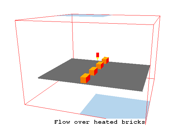
The following instructions will allow the user to set up and run the simulation of air in a cavity with heated bricks in VR.
The flow is three-dimensional and its geometry is shown below.

The geometry and simulation options are set up using VR Editor, the calculations are performed using the PHOENICS solver, EARTH, and the results are viewed using VR Viewer. Velocity, pressure and temperature will be simulated.
The initial and external temperature is 20 deg C. Buoyancy effects are significant due to the localised heating of the air around the blocks.
From the system level:
To enter the PHOENICS-VR environment, click on the PHOENICS icon on the desktop, or click on Start, programs, PHOENICS, PHOENICS.
In PHOENICS-VR environment,
Start with an 'empty' case - click on 'File' then on 'Start New Case', then on 'Core'', then click on 'OK'; to confirm the resetting.
To enter VR Editor:
This is the default mode of operation.
Set the domain size, and activate solution of variables:
Click on 'Main Menu' and then on 'Geometry'.
Change the Z-Domain Size to 0.7 m.
Click 'OK' to close the Grid mesh settings dialog.
Click on 'Models'.
Leave the 'solution for velocities and pressure' ON.
Click on 'energy equation' and
select 'Temperature' as energy formulation.
Click 'Properties'. Select '2 Air using Ideal gas Law, STP' as the domain material (it is in the Gases section).
Click 'Sources', and turn Gravitational forces ON. The Density_difference method will be automatically selected, and the Reference density will be automatically set from the ambient temperature and pressure on the Properties panel.
Gravity acts in the -Z direction, so make sure the X and Y components are set to 0,0 and the Z component is -9.81.
Turn 'Buoyancy effect on turbulence' ON.
Create the internal surfaces of the domain:
Click on 'Domain Faces'.
Set 'Wall' to 'Yes' for the Xmin, Xmax, Ymin, Ymax, Zmin and Zmax faces.
Click on 'OK' to close the Domain Faces Dialogue Box, and 'OK' again to close the reminder to set / check boundary conditions. We will set the wall temperatures shortly.
Click on 'OK' to exit the Main Menu.
Click 'Reset' on the Movement control panel, then 'Fit to window' to re-scale the view to fit the geometry.
Create the objects making up the scene
Click on the 'Object Management' button (O on the toolbar or
on the hand set). This will display a list of objects. The current objects are the domain boundary plates.
Select all the PLATE objects, then right-click and 'Open object dialog'.
Click 'Attributes', then for 'Energy Source' select 'Surface Temperature' and set the temperature value to 20.
Click 'OK' to close the Attributes dialog, then 'OK' to close the Object Specification dialog. Click 'Yes' to propagate the change to all the selected objects. This will set the surface temperature of all the domain-edge plates to 20.
With all six plates still selected, right-click and 'Hide objects'. This will prevent the plates from obscuring the inside of the domain.
Create the horizontal plate:
Click on 'Object', 'New', 'New object', 'Blockage'.
Change name to PLATE.
Click on 'Size' to set the SIZE of object as:
Xsize: 0.7
Ysize: 0.9
Zsize: 0.01
Click on 'Place' to set the Position of object as:
Xpos: 0.15
Ypos: 0.05
Zpos: 0.19
Click on 'General'.
Click on 'Attributes', then on 'Other materials', 'Solids' and select the material as STEEL.
Click on 'OK' to exit the Attributes menu and on 'OK' to exit the Object Dialogue Box.
Create the first brick:
Click on 'Object', 'New', 'New object', 'Blockage'.
Change name to BRICK1.
Click on 'Size' to set the SIZE of object as:
Xsize: 0.1
Ysize: 0.05
Zsize: 0.05
Click on 'Place' to set the Position of object as:
Xpos: 0.15
Ypos: 0.45
Zpos: 0.2
Click on 'General'.
Click on 'Attributes' and define the material as BRICK (go to OTHER MATERIALS, SOLID then to BRICK).
Click on 'Adiabatic', and select 'Fixed Heat Flux'
Set the heat flux to 30 W.
Click on 'OK' to close the Attributes menu.
Click on 'OK' to close the Object Dialogue Box.
Create the remaining bricks by arraying:
Check that the first brick built is still selected and appears with white contours, if not select it from the list in the Object management Dialog.
Now click on the 'Duplicate using array button', or select 'Object', 'Array object' from the Object Management Dialog menu bar. In either case, in the new dialogue box, set
Direction Dimension Pitch X 4 0.2 Y 1 0.0 Z 1 0.0 Click on 'OK' to exit from the Array Dialogue Box.
A row of bricks with the same attributes appears in the domain.
Create the fluid inlet;
Although fluid will enter through this boundary (due to buoyancy effects), we do not know the flow rate, but we do know the external pressure (and temperature). In PHOENICS all fixed-pressure boundaries are treated as OUTLET objects. The direction of flow is dictated by the local pressure difference.
Click on 'Object', 'New', 'New object', 'Outlet'. Select the Z plane for the outlet to lie in.
Change name to INLET.
Click on 'Size' to set the SIZE of object as:
Xsize: 0.4
Ysize: 0.5
Zsize: 0.0
Click on 'Place' to set the Position of object as:
Xpos: tick 'at end'
Ypos: tick 'at end'
Zpos: 0.0
Click on 'General'.
Click on 'Attributes' to define the external conditions.
Set the External turbulence to 'User-set' and leave the default values. This will give a turbulent viscosity roughly the same as laminar.
Leave the temperature at ambient, 20 degrees C for the inflow.
Click on 'OK' to close the Attributes menu, and on 'OK' in the Object Dialogue Box.
Create the fluid outlet:
This is also a fixed-pressure boundary.
Click on 'Object', 'New', 'New object', 'Outlet'.
Change name to OUTLET.
Click on 'Size' to set the SIZE of object as:
Xsize: 0.4
Ysize: 0.5
Zsize: 0.0
Click on 'Place' to set the Position of object as:
Xpos: 0.0
Ypos: 0.0
Zpos: tick 'at end'
Click on 'General' then 'Attributes'.
Leave the default values in the Attributes dialogue box.
Click on 'OK' to exit from the Object Dialogue Box.
Setting the Probe Location
Before running the solver, it is a good idea to place the probe in a suitable place to monitor the convergence of the solution. Too close to an inlet, and the value will settle down very quickly before the rest of the solution. Placed in a recirculation zone, it may still show traces of change even though the bulk solution is converged. In this case, somewhere under the dividing plate is fine.
Click on the probe icon
on the toolbar or double-click the probe itself, and move the probe to X=0.5, Y=0.5, Z=0.3
Set the grid
Click on the 'Mesh toggle' button. The default mesh will appear on the screen. The orange lines are region lines, and denote the edges of the bounding boxes of each object. The blue lines are ordinary grid lines introduced by the auto-mesher.
The auto-mesher actually does quite a good job giving a mesh of 60 cells in X, 47 in Y and 52 in Z. This is rather too fine for the purposes of the tutorial, as the case would take too long to run.
For now, we will coarsen the grid in all 3 directions.
Right-click anywhere on the image, and the 'Auto meshing' dialog box will appear. Moving the slider to the left will increase the number of cells, moving it to the right will decrease the number of cells.
Select the Z direction. Move the slider to the right until there are 20 cells shown in Z. This will happen when the 'Minimum cell fraction' is around 3.6%.
Select the Y direction. Move the slider to the right until there are 26 cells shown in Y. This will happen when the 'Minimum cell fraction' is around 2.2%.
Select the X direction, and change the view slightly so that the X grid becomes visible. Move the slider to the right until there are 32 cells shown in X. This will happen when the 'Minimum cell fraction' is around 3%.
Click 'OK' to close the Auto meshing dialog.
The final mesh should look like this:
Click the mesh toggle to hide the mesh display.
Set remaining solution control parameters:
In the Main Menu, click on 'Numerics'.
Set the number of iterations to 750. This is still not quite enough for a fully-converged solution, but will give a good idea of the flow.
Click on 'Top menu' to return to the top menu.
Click on 'OK' to exit the Main Menu.
In the PHOENICS-VR environment, click on 'Run', 'Solver'(Earth), and click on 'OK'; to confirm running Earth.
In the PHOENICS-VR environment, click on 'Run', 'Post processor',then GUI Post processor (VR Viewer) . Click 'OK' on the file names dialog to accept the default files.
To view:
To select the plotting variable:
To change the direction of the plotting plane, set the slice direction to X, Y or Z ![]()
To change the position of the plotting plane, move the probe using the probe position buttons
 .
.
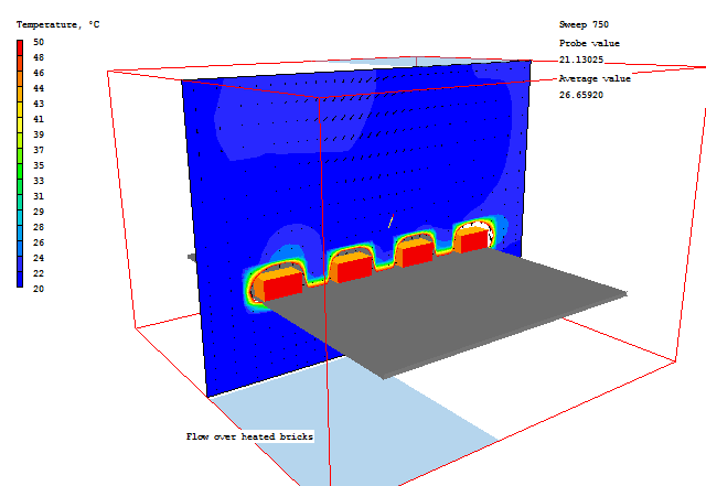
A typical plot from this case is:

Note that the top value on the temperature scale has been reduced to emphasise the thermal plume rising from the right-hand brick.
A typical streamline plot is shown here.
The 25 streamlines were started 'around a circle' of radius 0.1 in the Z plane, with the start point at (0.8,0.75,0.01).
In the PHOENICS-VR environment, click on 'Save as a case', make a new folder called 'BRICKS' (e.g.) and save as 'CASE1' (e.g.).