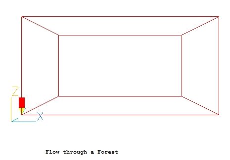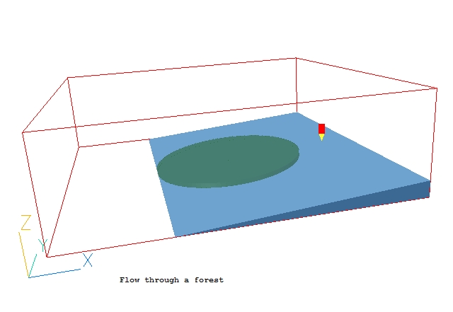
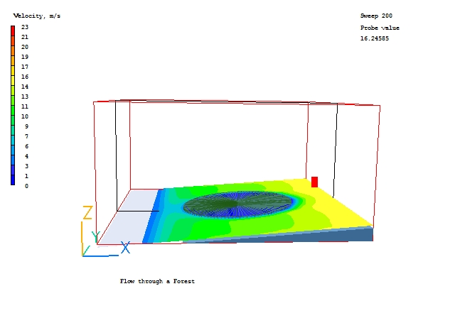
This workshop example shows how to use a FOLIAGE object to represent the flow through a block of trees - a forest. The case geometry is shown in the figure below. The shaded circle represents the trees. Velocity and pressure will be solved, and the flow is turbulent.
The domain is 1km wide, 1km long and 300m high. The forest is 500m diameter, 15m high and is located on a slope of 4°.
The airflow will be represented by a WIND object. The domain is located with the Y axis pointing North. The wind is blowing from the West with a reference velocity of 10m/s at a height of 10m.
From the system level:
To enter the PHOENICS-VR environment, click on the PHOENICS icon on the desktop, or click on Start, programs, PHOENICS, PHOENICS.
In PHOENICS-VR environment,
Start with an 'empty' case - click on 'File' then on 'Start New Case', then on 'Core', then click on 'OK' to confirm the resetting.
To enter VR Editor:
This is the default mode of operation.
Set the domain size and activate solution of required variables:
Click on 'Main Menu' and set 'Flow through a Forest' as the Title.
Click on 'Geometry'.
Change the X-domain Size to 1000.0 m.
Change the Y-domain Size to 1000.0 m.
Change the Z-domain Size to 500.0 m.
Click 'OK' to close the Grid mesh settings dialog.
Click on 'Top menu', then on 'OK'.
On the toolbar, click the down arrow next to
and select 'Fit to window'. The screen will appear blank - Click Settings, Near Plane, Reset. The screen should now look like this:
Create the Wind:
In the Object-management dialog, click on 'Object', 'New', 'New Object', 'Wind' to bring up the object specification dialog box.
Change name to WIND.
Click on 'Attributes' and set the 'Wind direction' to West. The 'Wind speed' and 'Reference height' are already correct, and the domain is aligned with the Y axis pointing North.
Change the 'Effective roughness height' from the default 'Open sea' to 'Parkland, bushes, numerous obstacles'. Change 'Include open sky' and 'Include ground plane' both to 'Yes'.
Click on 'OK' to close the Attribute menu, and on 'OK' in the Object Dialogue Box.
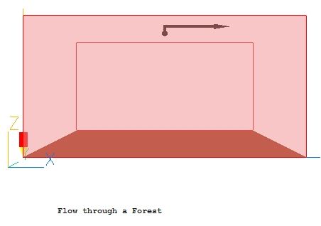
The screen should now look like this:
The wind object will now obscure the rest of the model, so right click it, either on the screen or in the Object management Dialog. In either case a context menu will appear - select 'Hide object' to remove it from the display. The wind is only hidden from view, it is still active in the model.
Create the slope:
'Object', 'New', 'New Object', 'Blockage'.
Change name to SLOPE.
The slope object represents the terrain the forest is growing on - any shape could be used, but for the tutorial we will assume that the slope is constant, so a wedge shape can be used. The slope will start at X=300m from the domain origin, so it will be 700m long. It will extend completely across the domain in the Y direction.
The angle of the slope is to be 4°. The height is thus 700*tan(4) = 48.95m
Click on 'Place' and set POSITION of object as:
Xpos: 300.0
Ypos: 0.0
Zpos: 0.0
Click on 'Size' and set SIZE of object as:
Xsize: tick 'to end'
Ysize: tick 'To end'
Zsize: 48.95
To change the shape of the slope from the default cube to the desired wedge, click 'Shape' then the button next to 'Geometry'. Navigate to public / shapes, and select wedge. The shape will change, but the slope will be in the wrong direction. We can fix this by flipping the shape within its bounding box until it looks right. Click 'Options', 'Rotation options' and increment 'Rotate object face' until the slope is in the right direction. This will happen at position 2 (and 22!). Click OK.
We need to set the roughness parameters of the slope to match the wind ground plane. Click 'General' then 'Attributes'. Set the 'Roughness' to 0.5m (same as shown on the wind dialog attributes), and the 'Wall function law' to 'Fully rough'. Click 'OK'.
Click on 'OK' to exit from the Object Dialogue Box.
Create the Forest:
'Object', 'New', 'New Object', 'Foliage'.
Change name to FOREST.
Click on 'Size' and set SIZE of object as:
Xsize: 500.0
Ysize: 500.0
Zsize: 15.0
Click on 'Place' and set POSITION of object as:
Xpos: 300.0
Ypos: 250.0
Zpos: 0.0
Set the rotation angle about Y to -4°.
Click on 'Shape'.
In 'Geometry', select /public/SHAPES/CYLINDER and click on 'Open', then 'OK' on the next dialog.
Click on 'Genera'. Define Type: FOLIAGE.
Click on 'Attributes' to open the Foliage Attributes menu.
Set the 'Leaf Area Index' to 'Very dense', and the Drag Coefficient to 'Conifers'.
Click on 'OK' to close the Object Dialogue Box.
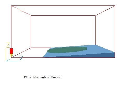
Click 'Options' and set the object colour to green.
The screen should now look like this:
Set the grid:
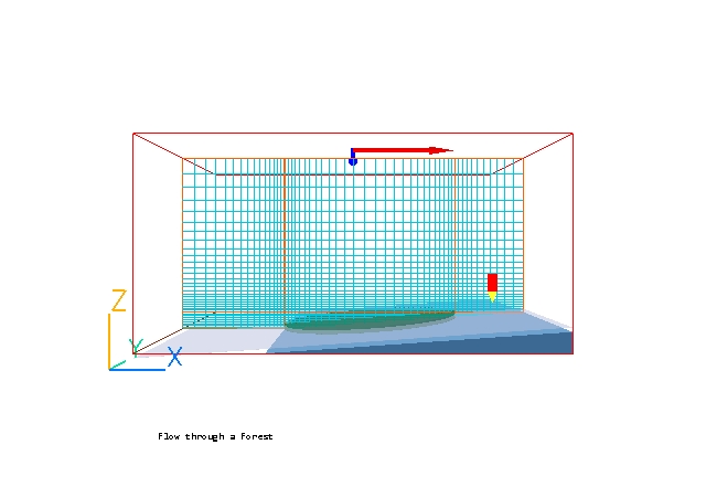
Click on the 'Mesh toggle' button. The default mesh (shown as blue and orange lines) will appear on the screen. The orange lines are 'regions', defined by the bounding boxes of the objects.
The mesh of 54 cells in X, 47 in Y and 35 in Z is adequate for this tutorial.
Click the 'Mesh toggle' again to turn off the mesh display.
Set the remaining solution control parameters:
Click on 'Main Menu' and then on 'Numerics'.
Set the number of iterations to 200.
Click on 'Top menu' to return to the top menu.
Click on 'OK' to exit the Main Menu.
Set the probe position
The probe is used to monitor the convergence of the solution. It is usually paced near the exit on the basis that if the flow has settled there, it has probably settled further upstream as well.
Double-click the probe itself, or click the probe icon on the toolbar. On the Probe Location dialog place the probe at X=900, Y=500, Z=70, then close the dialog.
In the PHOENICS-VR environment, click on 'Run', 'Solver'(Earth), and click on 'OK'; to confirm running Earth.
In the PHOENICS-VR environment, click on 'Run', 'Post processor',then GUI Post processor (VR Viewer) . Click 'OK' on the file names dialog to accept the default files.
To view:
To select the plotting variable:
To change the direction of the plotting plane, set the slice direction to X, Y or Z ![]()
To change the position of the plotting plane, move the probe using the probe position buttons
 .
.
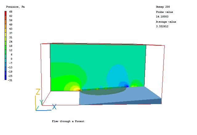
Typical plots from this case are:
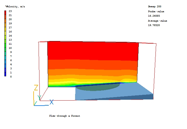
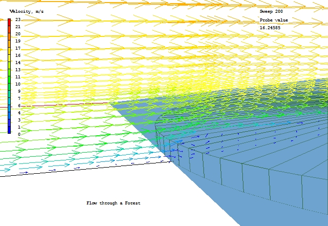
To plot, say, velocity contours on a plane parallel to the sloped surface of the terrain, proceed as follows:
In the Object-management dialog, click on 'Object', 'New' and 'Plotting Surface' to create a plotting plane and bring up its specification dialog box.
On the 'Place' tab rotate -4° about Y, then move the Z position down until the plane is where you want it, perhaps with the top of the forest showing through, around Z=24. Right-click the plotting surface and select 'Surface contour' from the context menu. The following image should appear (the FOLIAGE object has been set to 'Wireframe'):
Note that the plotting surface can be given any desired shape, including any 3D volume. Contours or vectors will appear on the surface of the object.
In the PHOENICS-VR environment, click on 'Save as a case', make a new folder called 'Forest' (e.g.) and save as 'CASE1' (e.g.).
Return to the Pre-processor (Run - Pre-processor - GUI) and change the Leaf Area Density and the Drag Coefficient to see what impact this has on the flow fields.