In this workshop contaminants will be introduced to the flow domain.
To start with, a contaminant of the same density as air at 20° C is introduced.
The workshop is then expanded to allow the introduction of a contaminant of a different density than that of air.
The method of introduction is through the Main Menu in the VR Editor
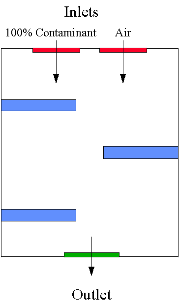
The two-dimensional flow domain used in this workshop is shown below.

Start with an 'empty' case - click on 'File' then on 'Start New Case', then on 'Core', then click on 'OK'; to confirm the resetting.
Set the domain size, and activate solution of variables
Click on 'Main menu' and set 'Introducing contaminants' as the Title.
Click on 'Geometry'
Change x-direction Domain size to 0.6
Click on 'OK' to close the Grid mesh settings dialog.
Click on 'Models' and leave 'Solution for velocities and pressure' to ON
Click on 'Solution controls / Extra variables'. You may have to click on 'page dn' if this button is not visible near the bottom of the panel. In the SOLVE entry box, type C1 and then click on 'Apply'.You will see a new variable called C1. This will represent the mass fraction of contaminant.
The default solution procedure is 'Slabwise' which in this case means on each Z line. To solve C1 more efficiently change the N in the third row (labelled Whole-field) for C1 to Y. This will activate a whole-field solution which will solve for C1 over the entire domain in one go. Click on 'Previous Panel'.
Click on 'Top Menu'.
Create the internal surfaces of the domain:
Click on 'Domain Faces'.
Set 'Wall' to 'Yes' for the Xmin, Xmax, Zmin and Zmax faces.
Click on 'OK' to close the Domain Faces Dialogue Box, and 'OK' again to close the reminder to set / check boundary conditions. The default conditions are fine.
Click on 'OK' to exit the Main Menu.
Click 'Reset' on the Movement control panel, then 'Fit to window' to re-scale the view to fit the geometry.
Create the CONTAMINANT INLET object.
Click on the 'Object Management' button (O on the toolbar or
on the hand set). This will display a list of objects. The current objects are the domain boundary plates.
Select all the PLATE objects, then right-click and 'Hide objects'. This will prevent the plates from obscuring the inside of the domain.
Click on 'Object', 'New', 'New object', 'Inlet', and select the Z plane for the inlet to lie in.
Change name to INL1.
Click on 'Size' and Place' in order to change the following to:
XPos: 0.1 XSize: 0.15
YPos: 0.0 YSize: 'To end'
ZPos: 1.0 ZSize: 0.0
Click on 'General'.
Click on 'Attributes' and change z-direction velocity to -1.0 m/s.
Enter 1.0 in the data entry box next to 'Inlet value' for C1. Click on OK.
Click on 'OK';.
Create the Air Inlet Object by duplication
Click on the above inlet object and make sure that it is selected.
Click on the 'Duplicate button' and 'OK' to confirm the action. The newly duplicated object will be at the the same place.
Use 'Position' movement button to change the following to:
XPos: 0.35
YPos: 0.0
ZPos: 1.0
Double click on the duplicated object to bring up the Object specification dialog box.
Change Name to INL2
Click on 'Attributes'.
Enter 0.0 in the data entry box next to 'Inlet value' for C1. Click on OK.
Click on OK
Create the OUTLET object.
Click on 'Object', 'New', 'New object', 'Outlet' and select the Z plane for the outlet to lie in.
Change name to OUTLET.
Click on 'Size' and 'Place' respectively to change the following to:
XPos: 0.2 XSize: 0.2
YPos: 0.0 YSize: 'To end'
ZPos: 0.0 ZSize: 0.0
Click on OK
Create the first Blockage.
Click on 'Object', 'New', 'New object', 'Blockage'.
Change name to BLOCK1.
Click on 'Size' and Place' respectively to change the following to:
XPos: 0.0 XSize: 0.3
YPos: 0.0 YSize: 'To end'
ZPos: 0.71 ZSize: 0.02
Click on OK
Create the second Blockage.
Click on 'Object', 'New', 'New object', 'Blockage'.
Change name to BLOCK2.
Click on 'Size' and Place' respectively to change the following to:
XPos: 0.3 XSize: 0.3
YPos: 0.0 YSize: 'To end'
ZPos: 0.44 ZSize: 0.02
Click on OK
Create the third Blockage
Click on 'Object', 'New', 'New object', 'Blockage'.
Change name to BLOCK3.
Click on 'Size' and Place' respectively to change the following to:
XPos: 0.0 XSize: 0.3
YPos: 0.0 YSize: 'To end'
ZPos: 0.16 ZSize: 0.02
Click on OK
Set the grid
Click on the 'Mesh toggle' button. The default mesh will appear on the screen. The orange lines are region lines, and denote the edges of the bounding boxes of each object. The blue lines are ordinary grid lines introduced by the auto-mesher. This grid is adequate for the tutorial, and does not need to be changed.
Set the remaining solution control parameters
Click on 'Main menu'
Click on 'Numerics'
Change 'Total number of iterations' to 750
Click on Top Menu/OK
Set the monitoring point.
Move Monitoring Point using the Position buttons to:
x = 0.34 y = 0.5 z = 0.5
In the PHOENICS-VR environment, click on 'Run', 'Solver'(Earth), and click on 'OK'; to confirm running Earth.
In the PHOENICS-VR environment, click on 'Run', 'Post processor',then GUI Post processor (VR Viewer) . Click 'OK' on the file names dialog to accept the default files.
To view:
To select the plotting variable:
To change the direction of the plotting plane, set the slice direction to X, Y or Z ![]()
To change the position of the plotting plane, move the probe using the probe position buttons
 .
.
(Click on the 'C' button and select C1 to display the contaminant distribution)
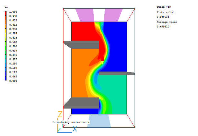
A typical plot from this case is:

In the PHOENICS-VR environment, click on 'Save as a case', make a new folder called 'Contaminants' (e.g.) and save as 'CASE1' (e.g.).
The density is to be calculated using the mass fraction in each cell, hence,
1/ρ = 1 / (C1/ρ1+C2/ρ2)
ρ = ρ1ρ2 / (ρ1+(ρ2-ρ1) C1) (1)
where, ρ1is the density of the contaminant (2 x 1.189 kg/m3), ρ2is the density of air (1.189 kg/m3), C1 is the mass fraction of contaminant and C2 is the mass fraction of air (actually 1-C1).
One of the available density relationships is 'Inverse linear'. This uses the following expression for density:
ρ = 1/(A + B φ) (2)
where ρ is the resulting density in each cell and φ is the variable.
Manipulating expression (1) to be in the same form as expression (2),
ρ = 1/((1/ρ2)+(ρ2-ρ1)/ (ρ1ρ2)C1)
Hence, A = 1/ρ2 ; B = (ρ2-ρ1)/ (ρ1ρ2); φ= C1
Click on 'Run - Pre processor - GUI Pre processor (VR-Editor)' to return to the Editor.
Set the required density relationship
Click on 'Main Menu'
Click on 'Properties'
Click on 'Edit properties of current material'
Click on Density dialogue box and select the INVERSE-LINEAR option. Click on OK.
Set Variable to: C1
Set A to : 1/1.189 = 0.841
Set B to : (1.189 - 2*1.189)/(2*1.189*1.189) = -0.4205
Set Storage for density to : ON
Click on Previous panel/Top Menu/OK.
In the PHOENICS-VR environment, click on 'Run', 'Solver'(Earth), and click on 'OK'; to confirm running Earth.
In the PHOENICS-VR environment, click on 'Run', 'Post processor',then GUI Post processor (VR Viewer) , and view the velocity vectors, contours and isosurfaces.
Click on the 'C' button and select C1 to display the contaminant distribution.
Click on the 'C' button and select DEN1 to display the density distribution.
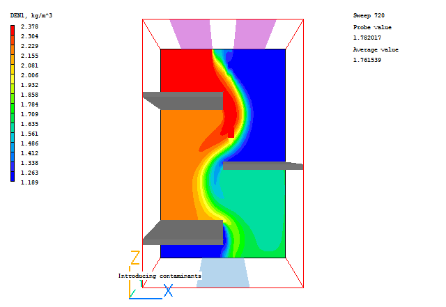
The density contours plot from this case is:

In the PHOENICS-VR environment, click on 'Save as a case', make a new folder called 'CONTAMIN' (e.g.) and save as 'CASE2' (e.g.).