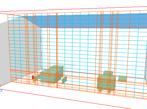
The PHOENICS Satellite module possesses an auto-meshing feature. By default it generates a grid from what it finds in the > OBJ lines in the Q1 file which has been presented to it, based upon a maximum cell size (as a fraction of the domain size), and a maximum change in cell size across region boundaries.

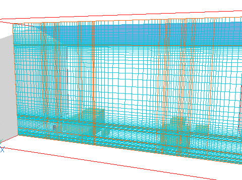
This default grid can, and often should, be modified by the user. The following picture shows how the above-shown grid has been further refined by the user's having increased the number of grid intervals per region:

Let the following image serve as a reminder: if the man and the stick appears in the Q1 as separate objects, the automesher devotes as many cells to the stick as to the man.

Click here for further information.