Although many excellent geometry-creation programs exist, it is sometimes convenient to be able to create the surface geometry of a desired object without using such a program; and it is certainly useful to understand how such a geometry could be made if the occasion arose.
One way of doing so is to use a simple Fortran (or other high-level-language) program. This is what will now be illustrated, by reference to the creation of a frustrum of a thick-walled cone.
An object can be represented by facets distributed on the outer surfaces of the object. In order to write a data file, the first task is to define the object in question by creating facets around its outer surface.
Each facet should be built from four points. Triangular facets can be made by repeating one of the points.
This figure

The location of each point is determined by its cartesian coordinates within a one-meter-cube "bounding box". These are recorded in an ASCII file, with extension .dat.
The file /phoenics/d_satell/d_vrgeom/Basic_Shapes/box.dat is as follows:
         8
      0.0000E+00  1.0000E+00  0.0000E+00
      1.0000E+00  1.0000E+00  0.0000E+00
      1.0000E+00  1.0000E+00  1.0000E+00
      0.0000E+00  1.0000E+00  1.0000E+00
      1.0000E+00  0.0000E+00  0.0000E+00
      0.0000E+00  0.0000E+00  0.0000E+00
      1.0000E+00  0.0000E+00  1.0000E+00
      0.0000E+00  0.0000E+00  1.0000E+00
         6
         2     1     4     3    48
         5     2     3     7    49
         6     5     7     8    48
         1     6     8     4    49
         8     7     3     4    50
         1     2     5     6    50
which corresponds to the following picture:
The significances of the numbers in the file are as follows:
Such files can be easily created or modified by way of an editor; but, if this is to be attempted, it is wise to add annotations (which will not affect the usability of the file) as follows:
         8                              point               Y
     0.0000E+00  1.0000E+00  0.0000E+00   1        .4--------.3
     1.0000E+00  1.0000E+00  0.0000E+00   2      .         .  !
     1.0000E+00  1.0000E+00  1.0000E+00   3  Z  8---------7   !
     0.0000E+00  1.0000E+00  1.0000E+00   4  !  !         !   !
     1.0000E+00  0.0000E+00  0.0000E+00   5  !  !   1     !  .2
     0.0000E+00  0.0000E+00  0.0000E+00   6  !  !         !.
     1.0000E+00  0.0000E+00  1.0000E+00   7  !  6---------5
     0.0000E+00  0.0000E+00  1.0000E+00   8  O------------->X
         6
         2     1     4     3    48
         5     2     3     7    49
         6     5     7     8    48
         1     6     8     4    49
         8     7     3     4    50
         1     2     5     6    50
Two examples of files created by editing cube.dat are:
cencube1.dat and
cencube2.dat.
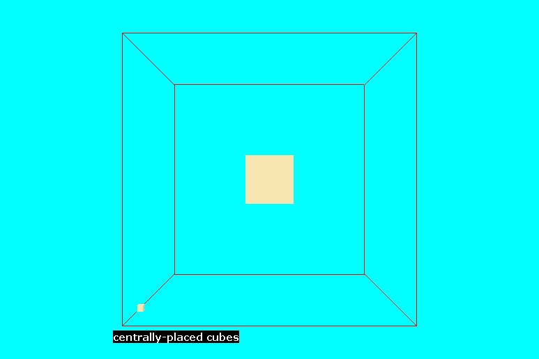
The first reduces the size of the cube, by making the lower and upper limits of the vertex coordinates 0.4 rather that 0.0 and 0.6 rather than 1.0; and this also has the effect of placing the reduced-size cube centrally within its 'bounding box'.
The second enlarges the size of the box ten-fold, so that, when it is brought by the VR-Editor into the 1m-by-1m-by-1m default domain, the shrinkage which the editor imposes by default is cancelled.
The two objects therefore have the appearance shown

Click here for access to other .dat files,
To create, by "hand-editing", a file which would describe a complex many-faceted object would be very tedious; therefore the use of a Fortran program has much to recommend it.
How to do so is best seen by inspection of the following example, which can be used to
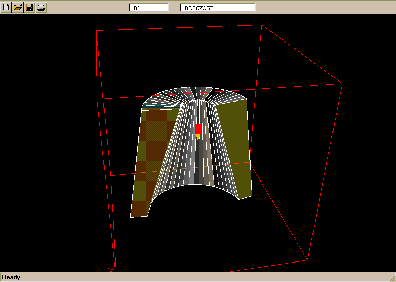
create a sector of the cone frustrum illustrated

The Fortran program which creates objects such as

The parameters which describe precisely which member of the class of thick-walled cone frustra is to be produced are supplied by editing the file "frustrum", which is also to be found in the directory /phoenics/d_utils/d_vrgeom . It is as follows:
       frustrum    variable =  meaning
       0.8         boufr    =  bottom outer radius
       0.6         binfr    =  bottom inner radius
       0.6         toufr    =  top outer radius
       0.2         tinfr    =  top inner radius
       24          nsides   =  number of facets
       0.45        angfac   =  proportion of 2PI
       0.25        angf     =  starting angle
       0.0         zpf      =  z location of bottom of frustrum
       1.0         zpl      =  z location of top of frustrum
       -1          isign    =  1 for opaque, -1 for transparent
It is only the left-hand-column entries which are read by the Fortran program; the remaining entries are comments serving to assist the user of the file.
It should be noted that, because the dimensions of the bounding box can be changed once the object has been loaded into the VR Editor, it is only the ratios of the dimensions which are of importance.
The directory /phoenics/d_utils/d_vrgeom also contains the following files, the sizes of which are indicated merely for interest.
       FRUSTRUM DAT         7,029
       FRUSTRUM EXE       244,736
       FRUSTRUM               510
       FRUSTRUM FOR         5,467
       FRUSTRUM OBJ        11,837
       NEWFRUST BAT            56
       BLDFRUST BAT           259
Frustrum, and frustrum.for have already been mentioned. Here attention is drawn to the two utilities, namely:
The frustrum.dat
file is too long to insert here; but the following extracts are
worth commenting upon:
(a) at the top,
   100
      7.90674E-01 5.74221E-01 0.00000E+00
      7.79935E-01 6.07872E-01 0.00000E+00
      7.65316E-01 6.40027E-01 0.00000E+00
which indicates that 100 points are in question;
         98
          1     2    27    26   -21
         26    27    77    76   -22
         76    77    52    51   -23
         51    52     2     1   -24
          2     3    28    27   -25
which indicates that there are 98 facets, and that the colours are 'transparent' (because their colour numbers are negative); and (b) in the middle,
         74    75    25    24  -116
          1    26    76    51  -117
         25    75   100    50  -118

      24  1  2  3  4  5  6  7  8  9 10 11 12 13 14 15 16 17 18 19 20 21 22 23 24
which indicates that all 24 orientations are allowed.
All is therefore perfectly understandable; but it is evident that even such a simple body requires a geometry-definition file of significant size; so editing by hand is out of the question.
Users of PHOENICS VR frequently bring new objects into their working domain and then change their position, size and orientation by way of the controls which are provided.
This is not always convenient; and, if the object is being "custom-made", it is not necessary. This will now be explained and illustrated.
Whereas the data required by frustrum.exe were supplied to it by way of a file which was read at the start of execution, the more-numerous data items required by chamber.exe are supplied via DATA statements in the Fortran file.
The difference is merely a matter of choice. Compilation and linking
being almost instantaneous for such a small program, time-saving is
not an issue.
5.4 The resulting .dat file
This is too large to show here.
It has been shown that the method of describing geometries, for display via PHOENICS-VR, is extremely simple.
Those therefore who possess both an elementary knowledge of Fortran and a sufficient grasp of how objects can be mathematically defined, can create many new objects simply by modifying slightly the examples which have just been described.
However, they may prefer to employ the PHOENICS ShapeMaker utility.
This program, which may be run either interactively or in command-file mode, allows objects of many different shapes and sizes to be created.