The case below exemplifies how the IPSA method built in PHOENICS for two-phase calculations can be applied to steady boiling in pipe. The cylindrical-polar coordinate system is used and the flow is laminar. The heat source is supplied along a part of the pipe wall.
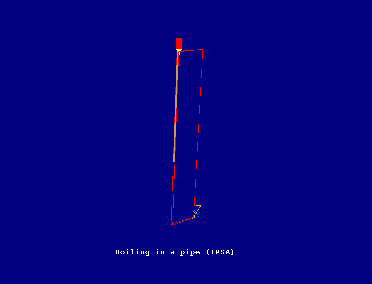
The geometry is shown below:

A complete step-by-step guide, showing how to set the case from the default mode of operation, is provided.
From the system level:
To enter the PHOENICS-VR environment, click on the PHOENICS icon on the desktop, or click on Start, programs, PHOENICS, PHOENICS.
From the commander level:
To enter the PHOENICS-VR environment, click on the 'Run vre' icon in the left column.
In PHOENICS-VR environment,
Start with an 'empty' case - click on 'File' then on 'Start New Case', then on 'Core'', then click on 'OK'; to confirm the resetting.
To enter VR Editor:
This is the default mode of operation.
Set the domain size and grid numbers:
Click on 'Menu' (Main Menu) on the VE-Editor panel; and set 'Boiling in a pipe (IPSA)' as the Title.
Click on 'Geometry'.
Click on 'Cartesian' under co-ordinate system; and select 'Cylindrical-polar' and then on 'OK'.
Leave 'Inner radius' at 0.0 and 'tolerance' at 1.e-3.
Change the x-domain size to 0.1 radians.
Change the y-domain size to 0.0587 m.
Change the z-domain size to 0.375 m.
Set 'number of cells' to 1 in x-direction, 10 in y-direction and 20 in z-direction.
Click on 'OK' to close the Grid mesh settings dialog.
Click on 'OK' to exit from 'Menu'.
Click on 'Reset' button on the movement panel.
Click on 'Fit to Window'. You may need to click on 'zoom out' button if the geometry does not appear on the screen.
Use Arrow buttons on the movement panel to position the Z-direction of the coordinate upright and Y-direction pointing to the right, as in the picture above.
Activate solution of the required variables and models
Click on 'Menu'; and the on 'Models'.
Change the simulation from 'One phase' to 'IPSA_FULL'.
Leave 'Solution for velocities and pressure' to ON.
Click on ENERGY EQUATION; and then choose ENTHALPY and toggle STATIC to TOTAL.
Click on 'settings' for IPSA_FULL
Set the interphase coefficient (CFIPS) to 2500.
Set the interphase mass transfer coefficient (CMDOT) to HEATBL and turn 'Store' to 'ON'.
Set the interphase heat transfer coefficient (CINT) to 10 for both H1 and H2
Click on 'Previous panel'.
Specify properties
Click on 'Properties'.
Turn 'Use property table' to OFF.
Set the density of phase 1 to 749.94 kg/m3.
Set the density of phase 2 to 35.55 kg/m3.
Set interphase properties (PHINT) to 0.1 for H1, 1.513E6 for H2.
Set Initial values
Click on 'Initialisation'.
Set the following initial values
- 2.0 m/s for W1
- 2.0 m/s for W2
- 0.999 for R1
- 1.E-4 for R2
- 1.513E6 J/kg for H2
Set gravitational force
Click on 'Sources'.
Turn 'Gravitational forces' to 'ON'
Change Buoyancy model to 'CONSTANT'
Set gravitational acceleration to -9.81 m/s2 in Z-direction.
Enter numerical settings
Click on 'Numerics'.
Set 'Total number of iterations' to 250.
Click 'Relaxation control' and set 'Automatic convergence control' to OFF
set the following values:
- 0.1 for V1 (False time-step)
- 0.1 for W1 (False time-step)
- 0.1 for V2 (False time-step)
- 0.1 for W2 (False time-step)
- -0.25 for R1 (Linear relaxation)
- -0.25 for R2 (Linear relaxation)
- 1.0 for H1 (False time-step)
- 1.0 for H2 (False time-step)
- -0.1 for CMDO (Linear relaxation)
Click 'Previous panel'
Click on 'Top menu' and then on 'OK' to exit from 'Menu'.
Create Objects and specify boundary conditions
Create the Inlet
Click on 'Settings', 'New' and 'New Object'.
Change name to INLET.
Click on 'Size' and set Size of the object as:
Xsize: 0.1
Ysize: 0.00587
Zsize: 0.0
Click on 'General'.
Define Type: INLET.
Click on 'Attributes'
Change the Inlet density to 'Dens*Vol Frac' (Density*Volume fraction)
Set enthalpy to -60000 J/Kg.
Set velocity in Z-direction at 2 m/s.
Click on 'OK' twice to exit from the Objectspecification Dialogue Box.
Create the heat source
Click on 'Settings', 'New' and 'New Object'.
Change name to Heater.
Click on 'Size' and set Size of the object as:
Xsize: 0.10
Ysize: 0
Zsize: 0.225
Click on 'Place' and set Position of the object as:
Xpos: 0.0
Ypos: 0.0587
Zpos: 0.15
Click on 'General'.
Define Type: PLATE
Click on 'Attributes'.
Change Energy source to 'Surface enthalpy' and set the value to 1.366E7 J/Kg
Click on 'OK' and check the position and size again.
Click on 'OK' to exit from the Object Dialogue Box.
Create the outlet
Click on 'Settings', 'New' and 'New Object'.
Change name to Outlet.
Click on 'Size' and set Size of the object as:
Xsize: 0.1
Ysize: 0.00587
Zsize: 0.0
Click on 'Place' and set Position of the object as:
Xpos: 0.0
Ypos: 0.0
Zpos: 0.375
Click on 'General'.
Define Type: OUTLET
Click on 'Attributes'
Set Ph 1 coefficient to 20, and Ph2 coefficient to 1.0
Click on 'OK' twice to exit from the Object Dialogue Box.
In the PHOENICS-VR environment, click on 'Run', 'Solver'(Earth), and click on 'OK'; to confirm running Earth.
In the PHOENICS-VR environment, click on 'Run', 'Post processor',then GUI Post processor (VR Viewer) Viewer)'. Click 'OK' on the file names dialog to accept the default files.
To view:
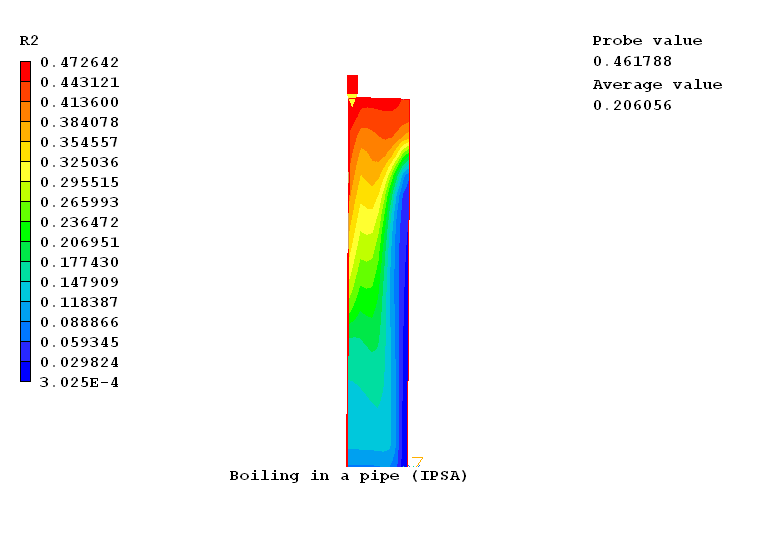
The image below shows the phase 2 (Steam) volume fraction distribution.

To select the plotting variable:
To change the direction of the plotting plane, set the slice direction to X, Y or Z
![]()
To change the position of the plotting plane, move the probe using the probe position buttons
 .
.
In the PHOENICS-VR environment, click on 'Save as a case', make a new folder called '2PHASE', select the new folder, and save as 'IPSA'.