[Chapter 2 of the lecture CAD to SFT.
Click here for the start of the lecture]
2.2 An aeronautical example: the 3-part airfoil, with PARSOL and fine-grid embedding
2.3 A test of PARSOL; the turn-around duct
2.4 Flow around an automobile, with PARSOL and fine-grid embedding; and other PARSOL examples
2.5 Concluding remarks about CAD to CFD
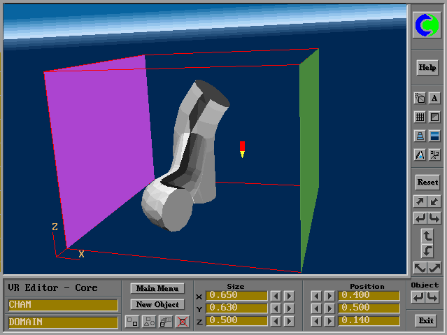
CAD packages are used for defining the shapes and sizes of the objects of which the fluid-flow or solid-stress performance is studied.
The definitions can be expressed in various formats, of which IGES, DXF and STL are examples.
Here the STL (ie STereo-Lithographic) format is considered. It describes solid bodies by defining the locations of their surfaces, these surfaces being made up of an array of approximating triangles, each of which shares its edges with (only) one other.
There exist translator programs which can effect IGES-to-STL, DXF- to-STL and similar conversions. CADfix, from FEGS Ltd, is one.
The STL format is a convenient one for representing objects visually in "virtual-reality"-type data-input interfaces for CFD codes.
Such interfaces can immediately accept and display the objects which the CAD users have created; and they provide their own users with the further abilities:-
Fig. 2.1-1 a CAD-generated object after transfer into PHOENICS-VR.
Click here for an example of DXF-to-VR conversion
Click here for a description of the DXF-to-VR converter program
Click here for an IGES-to-VR example
Once all the data have been inserted, and the user is satisfied that the problem specified is the one which he wants to solve, all that should be necessary is to click on the EXIT button; then the data should be exported to the equation solver; and, after the requisite "number-crunching" time, the results should be returned to the VR Interface.
The "should be" implies the condition "if the user is not a specialist in computational fluid dynamics, but simply wants to get the results of the computations, as quickly as possible, in a form which he can understand".
This condition is frequently satisfied; and it will be almost universally so in the future, as the CAD-to-CFD traffic increases.
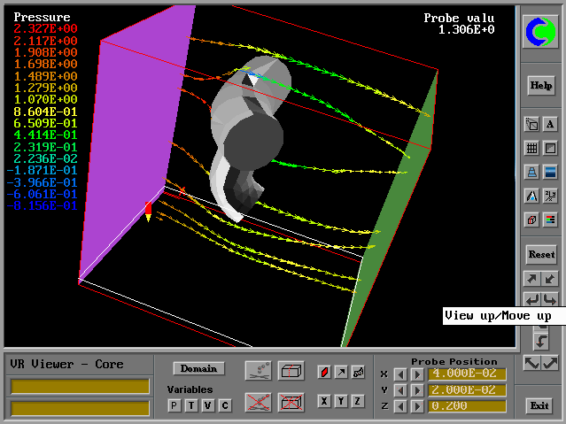
Fig. 2.1-2 shows some of the results of the flow simulation corresponding to the data-input specification of Fig. 2.1-1. The VR-viewer is capable of showing vectors, streamlines, contours and iso-surfaces.
Fig. 2.1-2 The same object in the VR-viewer
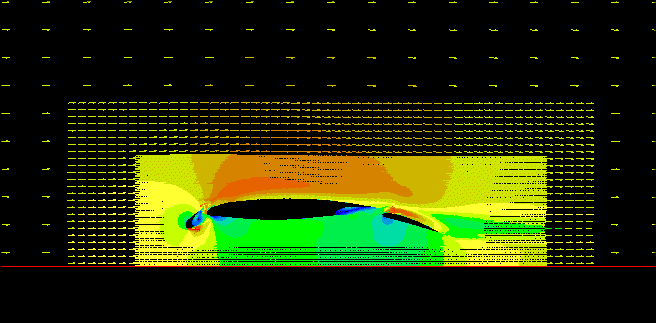
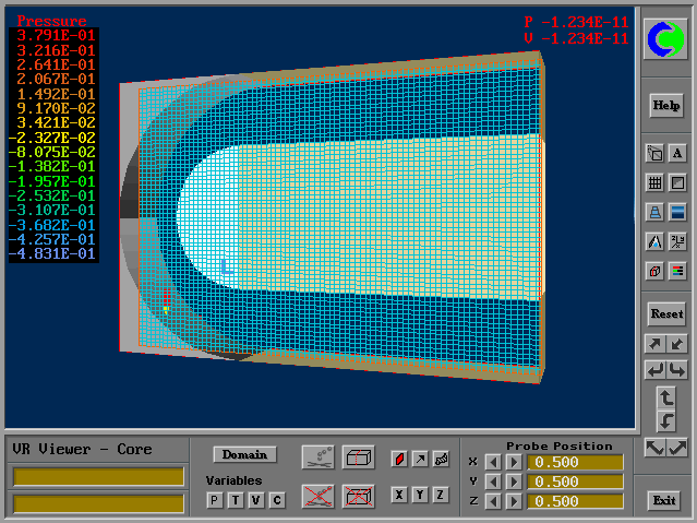
In order to show that it is often unnecessary, a two-dimensional example will be shown, in which a three-part airfoil is represented in a cartesian grid possessing three levels of fineness.
The grid-refinement is easily effected by way of mouse-clicks, and keyboard-entered refinement ratios, in the VR-editor operation.
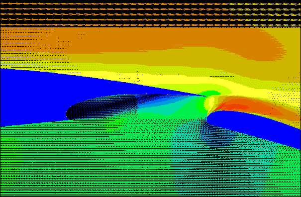
The first of the following two pictures shows the airfoil itself; and the second shows a close-up of part of it, and of the associated grid.
Fig. 2.2-1 The three-part airfoil
Fig. 2.2-2 The three-part airfoil;close-up
There was a time at which inaccuracies of solution were generated in those cells of the cartesian grid which were cut obliquely by the surface of immersed solids.
Taking extra care about the formulation of the equations relating to such cells has however removed the inaccuracies. Relevant references are Yang et al, 1997 a,b,c; and PHOENICS has its own version of the technique, called PARSOL (standing for PARtial SOLid).
When appropriately implemented, computer codes which employ such techniques can provide solutions of the fluid-flow equations of a quality which is equal to those which employ body-fitted grids.
Because of their superior ease of use, such codes make travel along the CAD-to-CFD road especially smooth.
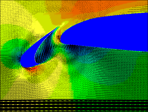
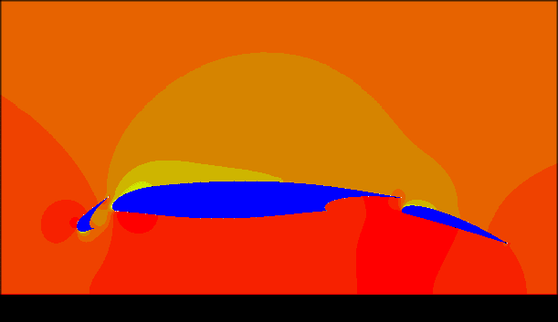
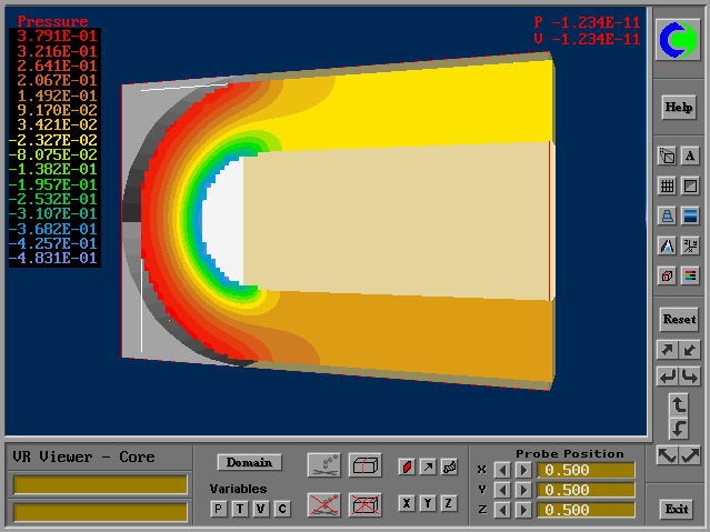
The next four pictures show results for the three-part airfoil.
Fig. 2.2.3a Contours of velocity.
Fig. 2.2.4 Contours of pressure.
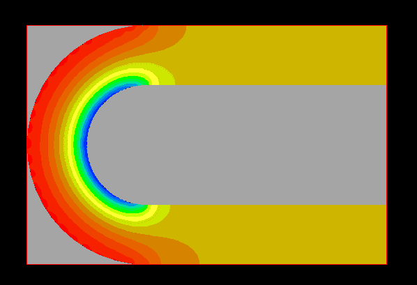
As a further demonstration of the accuracy which the cut-cell techniqe can provide, the next two pictures show the results of a study of the inviscid flow in a "turn-around" duct.
The first picture shows the grid, which is rather coarse.
The second shows the computed pressure distribution, albeit first with an
early version of the VR-Viewer, which could not do reflect the cut cells
properly. How much depends on the Viewer is shown by a supplementary
picture.
This distribution should be perfectly symmetrical; and the one shown
is very nearly so.
Fig. 2.3-2a The pressure distribution (with early Viewer)
Fig. 2.3-2b The pressure distribution (with improved Viewer)
The present author knows of no code employing a body-fitted grid with a comparable number of cells which can procure superior symmetry.
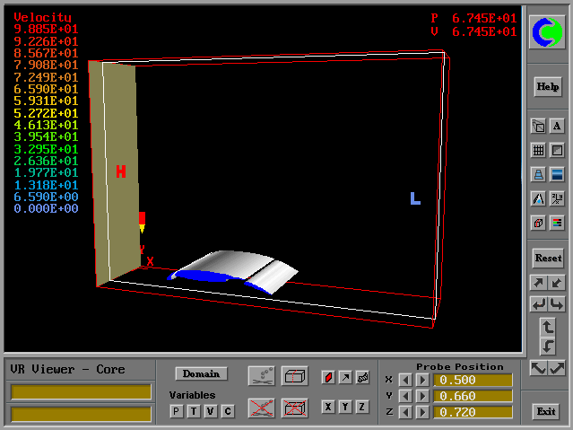
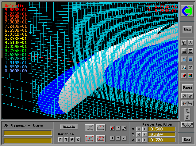
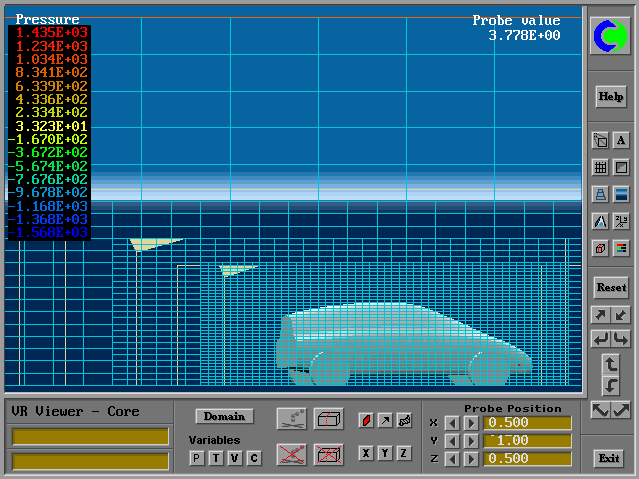
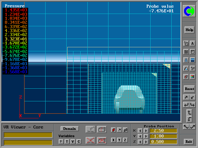
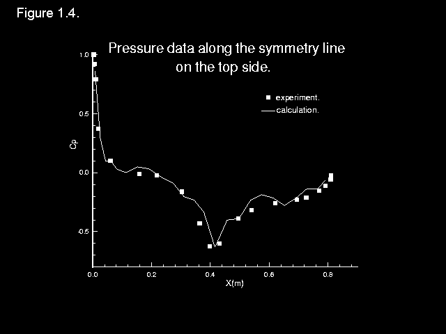
As a final example, a few pictures are shown from a study, which employed the techniques just described, of the flow around the automobile body specified as a benchmark problem for the 1996 WUA Conference.
These pictures illustrate:-
Fig. 2.4-1 the automobile in the VR-viewer
Fig. 2.4-2 the automatically-created grid, side view
Fig. 2.4-3 the automatically-created grid, end view
Fig. 2.4-4 comparison with the experimental data
Click here for more examples of PARSOL
The foregoing arguments and examples, while not being conclusive, lend plausibility to the following suggestions:
A competent user of CAD packages who also understands fluid and heat flow from a practical viewpoint, can reasonably expect to become a fluid- and heat-flow predictor after very little acquaintance with the relevant software,
The STL format, being common to the CAD, Virtual Reality and CFD packages, is worth bringing into greater prominence. The good accuracy obtained with cartesian grids, combined with fine-grid embedding and the "cut-cell" technique, may render the more expensive body-fitted-coordinate formulation unnecessary.
When combined with simultaneous solid-stress analysis, to be
described in the next section, a very considerable advance in
the designer's powers will have been achieved.
Back to top