The use of CFD in the design and development of gas-turbine
combustors
by
Brian Spalding, of CHAM Ltd
January, 1999
Abstract
Computational fluid dynamics has been used for predicting the perfomance
of gas-turbine combustors since the early 1970s; but its more extensive
use is hampered by two main factors, namely:-
the difficulty of creating computational grids which will adequately
represent the complex geometries of actual combustion chambers;
and
the uncertain reliability of its predictions in respect of the
production of undesired secondary products of combustion.
This lecture concerns the first of these; and it explains how a
newly-developed "cut-cell" technique, called PARSOL, enables
curved-surface geometries to be adequately handled by easy-to-create
cartesian or polar grids.
Coupled with another available technique, namely
fine-grid-embedding, PARSOL may provide an acceptable solution to
the grid-generation difficulty.
PARSOL has already been incorporated into PHOENICS, as has
fine-grid-emedding; and some applications to combustion-chamber flows
are described in the lecture.
PARSOL is however still being developed further. Some of the started
and planned further features are described.
Note: Figures, the titles of which are indicated by underlining,
are not provided in the printed paper. They may be inspected, together
with the text, on the web-site: www.cham.co.uk
1. Problems associated with the computer simulation of
gas-turbine combustion
(a) The historical perspective
Computational fluid dynamics has been used for predicting the perfomance
of gas-turbine combustors since the 1970s, the earliest paper known to the
author being Reference 1, in which a 7*7*7 (!) grid was used to solve the
equations for:
pressure;
three velocity components;
the two variables of the k-epsilon turbulence model;
the composite fluxes of the six-flux radiation model;
the enthalpy; and
the mixture fraction.
The SIMPLE algorithm was used for solving the coupled hydrodynamic
equations; and the mixed-is-burned hypothesis was employed.
At around the same time, the first papers were being published on how
the influences of the turbulence on the chemical reaction might be
taken into account, by way of the "eddy-break-up" [Reference 2] and
"presumed-PDF" [Reference 3] concepts.
(b) The current situation
Current uses of CFD by combustor developers employ essentially the
same quarter-century-old ideas, but with the
following differences:-
more sophisticated models of turbulence-chemistry interactions
are employed, such as:
"eddy-dissipation concept" [Reference 4],
"flamelet" [Reference 5],
"PDF-transport" [Reference 6], or
"multi-fluid" [Reference 7],
to enable chemical-kinetic knowledge to be utilised;
more sophisticated models of radiation are employed, such as:
"discrete-transfer"
[Reference 8] or
"discrete-ordinate" [Reference 9]
for
the better computation of the radiative contribution to the heat
transfer;
much larger numbers of computational cells are employed to enable the
complex geometries of real combustors to be adequately represented;
these geometries are frequently imported from CAD-software packages,
making it desirable for there to be an easy way of effecting the
CAD-to-CFD transition.
Despite the advances just alluded to, the use of CFD is far from
enabling extensive experimental testing to be dispensed with. The
reasons are:-
it remains difficult to create computational grids which will
adequately represent the complex geometries of actual combustion
chambers; and
CFD-based predictions remain insufficiently reliable in respect of the
concentrations of undesired secondary products of combustion, such
as smoke, and oxides of nitrogen.
The present author has addressed the latter difficulty in a two recent
papers [References 10 & 11]. The present paper is therefore directed
towards the first problem, i.e. that of grid generation.
Of these, and of their advantages and disadvantages, there is much
that can be said, but little that will procure agreement among the
specialists.
The present author's views are:-
unstructured body-fitted grids are more "fashionable" (in a sense
similar to that of "politically correct") than unstructured ones);
their only other appeal is that they may allow accurate simulation
of near-wall boundary-layer effects, possibly at the expense of
of reduced accuracy elsewhere;
their disadvantages in respect of:-
human expense during problem-set-up time and
computer-time expense during execution
are such that no-one would use them if equal accuracy were known to be
obtainable with structured cartesian or polar grids.
Recently, two developments have made the latter preference
realisable. They are:-
fine-grid embedding (i.e. FGEM); and
the "cut-cell" (i.e. PARSOL) technique.
The next section will be devoted to describing FGEM and PARSOL in
general terms; thereafter applications to gas-turbine combustors
will be presented.
2. The FGEM/PARSOL solution to the grid-generation
problem
To present the topic of this section, it is necessary to
introduce several ideas in quick succession, namely:-
Engineers designing equipment commonly employ
computer-aided-design (CAD) software packages for defining the
equipment shapes.
The output of their endeavours is embodied in the form of computer
files, having one of several standard formats, for example:-
STL (i.e. stereolithography),
IGES, or
DXF.
PHOENICS is able to read such files, and to import the so-defined
geometries directly into its own "virtual-reality" data-input
software module; whereafter boundary conditions of a CFD character
(e.g. flow rates and heat inputs) can be supplied.
The format employed for describing
objects in PHOENICS VR, ie by way of "facets", is very close to the
STL format; and translators for IGES and DXF have also been
created; so the CAD-to-CFD transition can be very speedily
effected.
In the most straightforward implementation, PHOENICS first sets up
a cartesian grid which fits exactly the "bounding boxes" of all the
objects in the space, and has a fineness which the user determines by
specifying the number of grid intervals in each direction.
PHOENICS then examines the facets defining the objects, and having
determined on which side of the facet the cell-centre lies, fills
the whole of the cell with solid or fluid.
The PHOENICS solver is additionally able to respond to user's
specifications of regions in which grid-refinement is thought to
be necessary, by means of what is called the FGEM (fine-grid
embedding) technique.
All that is necessary in order to use this is to:
define the size and location of the bounding box of the
grid-refinement region; and
define the refinement ratios to be employed in the three
different directions.
The PHOENICS solver has also been equipped with the PARSOL feature
which, whenever an object-defining facet intersects a
computational cell obliquely, calculates the intersections of the
facets with the cell edges and then does what is necessary to ensure that
the terms in the algebraic representations of the conservation
equations are properly modified.
FGEM and PARSOL can be used in combination to such effect that, it
may be argued, the case for using body-fitted coordinates is much
diminished.
How the CAD-to-CFD path can be quickly traversed by CAD-literate
engineers, by the use of PHOENICS, can be seen by clicking
here.
The capabilities of the FGEM and PARSOL techniques can be best be
displayed by a tour of the relevant parts of the PHOENICS
Applications Album, which can be entered by clicking
here.
Legitimate conclusions from detailed inspection of the
just-mentioned material appear to be:-
The CAD-to-CFD transition can indeed be swiftly made, entirely
without grid-creation difficulties.
The PARSOL technique, with or without FGEM, appears to be capable of
procuring solutions
of the hydrodynamic equations of an accuracy comparable with or superior
to what can be achieved by means of body-fitted grids, whether
structured or unstructured.
Fine-grid embedding permits the focussing of attention on regions
of especial importance; and such focussing is achieved by simple
mouse-clicking operations.
The examples which have been shown do not, however, include the
presence of thin walls, such as are of importance in
combustion-chamber simulations.
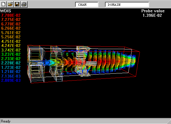
3. PARSOL applied to a 3D combustor
(a) The problem considered
In order to illustrate how PHOENICS can be used for simulating flows
within combustors having curved walls without use of
body-fitted coordinate grids, an idealized combustor model has been
created which exhibits all the main geometrical features, namely:-
enlarging, near-constant and then diminishing cross-section;
axial entry of two coaxial streams;
admission of additional air through film-cooling slots;
admission of secondary air through apertures in the wall:
The geometry has not in fact been created by means of a standard CAD
package, but rather by a stand-alone Fortran-program utility which
can make simple shapes very fast. However, that is not relevant to
the present demonstration of the ability of PHOENICS to handle
objects defined by facets, whatever their origin.
Figure 2, which is a
view of the interior of the chamber, seen from the outlet end;
Figure 3, which
is a similar view, but with more of the intervening solid "cut away";
Figure 4, in which
still more sight-obstructing material has been removed; and
Figure 5 which, because
the "viewing eye" has drawn nearer, and slightly changed the line of sight,
reveals more clearly:
the circular fuel entry and surrounding air entry on the left;
the annular film-cooling slot;
one part of the surrounding wall; and
the rectangular secondary-air-entry aperture which has been cut in it.
The flow is steady and turbulent, with use of the so-called LVEL
model for simplicity; heat transfer results from the fact that the
various streams enter at different temperature; but chemical
reaction has not been activated.
The same problem has been simulated in three different ways,
namely:-
with a mono-block cartesian grid;
with additionally an embedded fine grid; and
with PARSOL activated.
(b) The grid-generation problem
On this topic it perhaps suffices to say that there is no
grid-generation problem, for the user, because:
PHOENICS receives information about the shapes of the combustor
walls, and the apertures in them, from the "Virtual-Reality"
data-input module, sole screen-dumps from which constituted Figures t
to 5; and from this information it deduces which
computational cells are blocked by solid and which are not.
PHOENICS also detects whether regions have been specified as
requiring grid refinement, and does what is necessary without user
intervention.
When Parsol has been activated by the appropriate button-click
in the menu, the appropriate changes in the conservation equations
are made, automatically, within the PHOENICS solver.
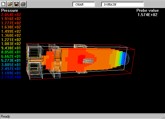
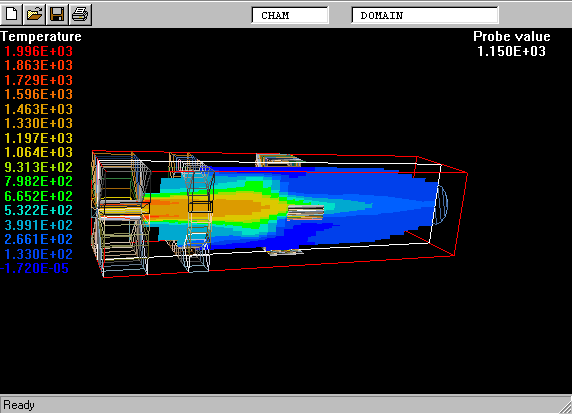
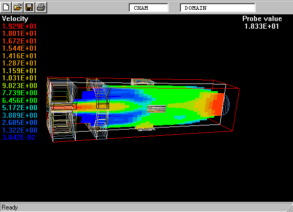
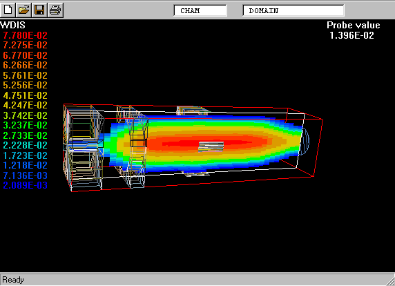
(c) Results of the stage 1 (mono-block-grid) calculation
The following Figures represent various aspects of the first-stage
solution, by way of "screen dumps" from the PHOENICS
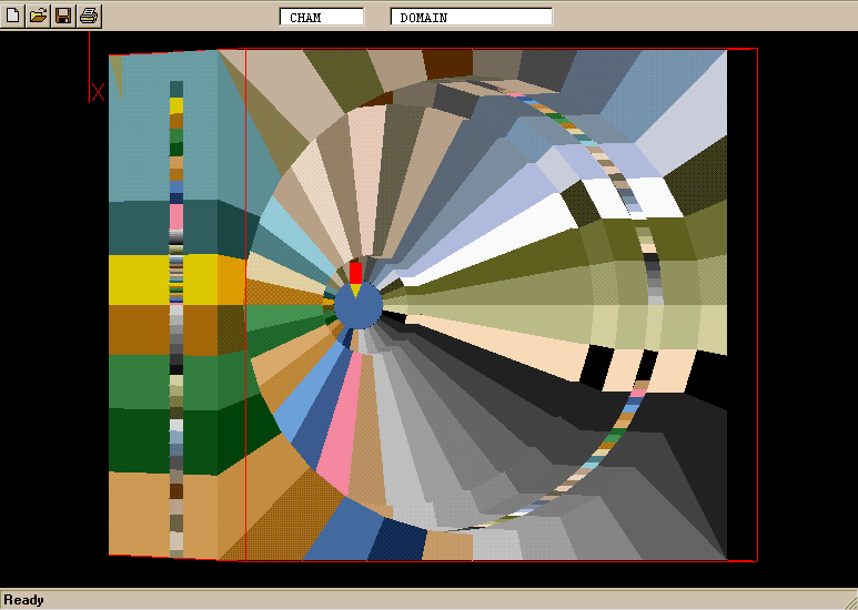
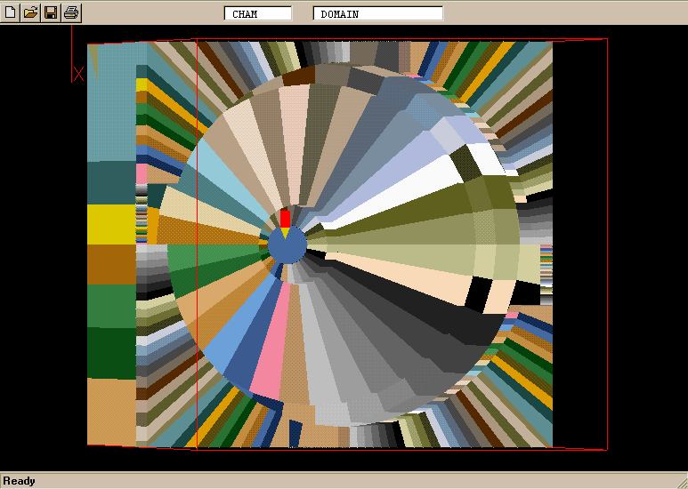
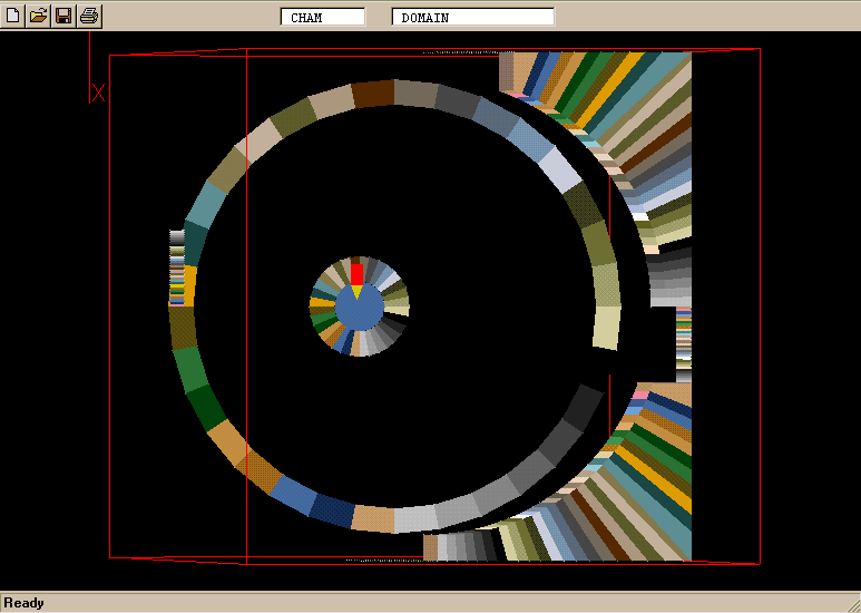
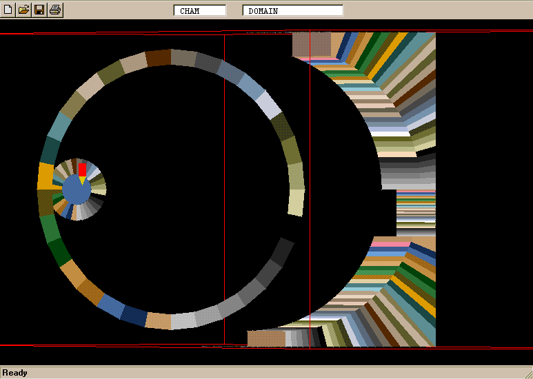
"Virtual-Reality" Viewer.
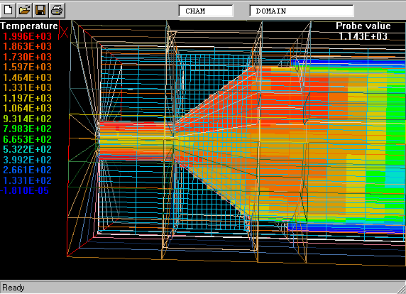
Noteworthy features are:
The physical plausibility of all results;
The ability of the viewer to display many different aspects of
the flow, in as much detail as can reasonably be required.
The somewhat disquieting "step-like" appearance of the curved
and sloping walls, which are probably associated with inaccuracies in
the solution.
[In parenthesis, it may remarked that these inaccuracies may not
be as great as those arising when badly-skewed body-fitted grids are
employed. The appearance of the steps is probably worse than their
effect.]
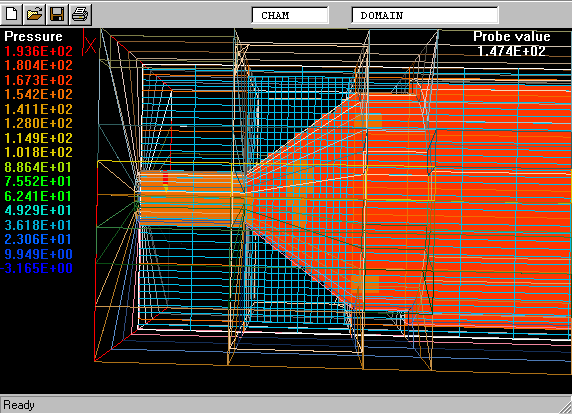
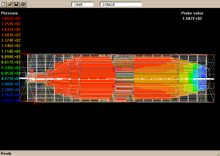
stage 1 pressures,
which shows the above-mentioned "step" effect.
It should be noted that chamber-wall-defining objects are shown only in
"wire-frame" view; and several have been hidden so that the contour
plots can be seen more clearly.
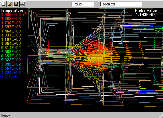
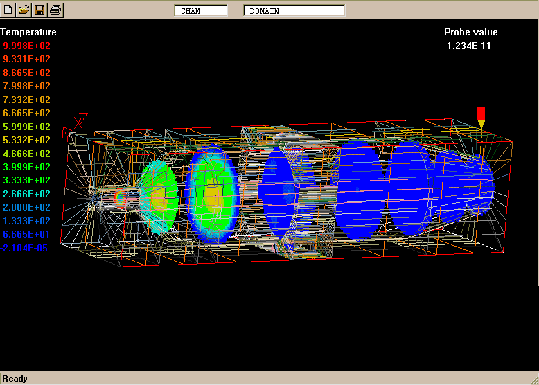
stage 1: temperatures, from the same viewpoint.
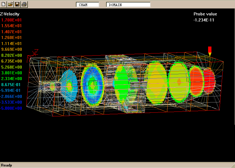
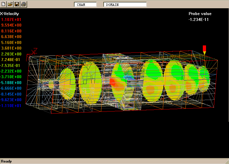
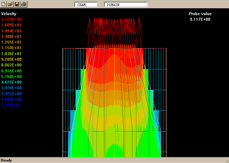
stage 1: velocities
, likewise.
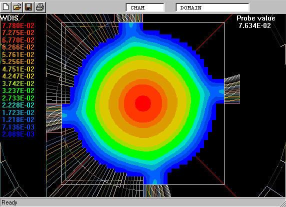
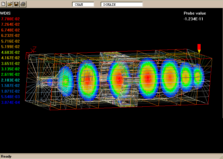
stage 1: wall distances
, likewise.
The values of distance to the wall are of couse needed by the LVEL model of
turbulence.
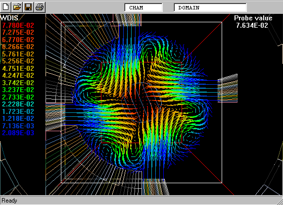
stage 1: vectors
of velocity, coloured, incidentally, according to wall distance.
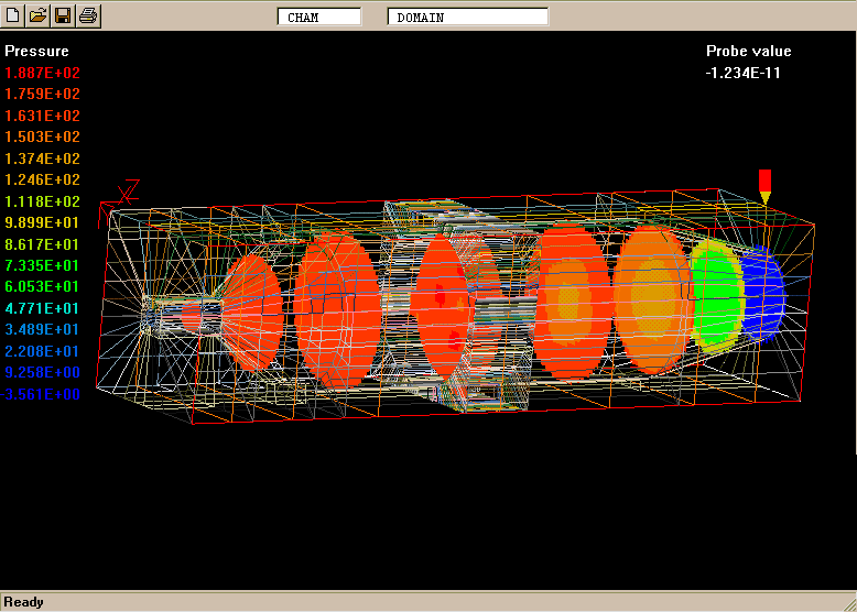
stage 1: wall distances
at the cross-section where the secondary air enters.
What is interesting is to note the near-circularity of all contours, apart from
the expected distortions near the apertures.
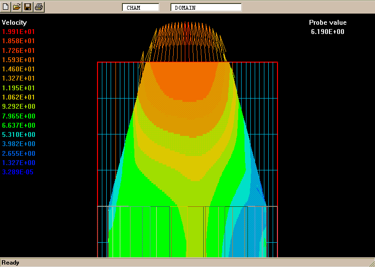
stage 1: vectors
of velocity at the same cross-section, where the influence is shown of the
swirl imparted by the secondary air.
Such results, it should be mentioned, are produced by PHOENICS on a Pentium 200
MHz PC in less than half an hour.
(d) Results of the stage-2 (FGEM) calculation
The following Figures represent various aspects of the second-stage
solution, by way of "screen dumps" from the PHOENICS
"Virtual-Reality" Viewer.
They focus attention on the conical area enlargement, where the fine
grid has been located.
stage 2: pressures ;
stage 2: temperatures ;
stage 2: vectors
Qualitatively, the results are similar to the previous ones; but the
fitting of the conical-divergence shape is obvously better because of the
fine grid is embedded there.
[Refinenment of this simple kind could, indeed, have been
effected more easily in mono-block mode. However, the purpose here
has been only to show how easily grid-refinement is effected, and
how it reduces the "step" effect.]
The following further results relate to another Stage-2
calculation in which the fine-grid region is moved to the air and
fuel inlet region.
Figure 6 :
Figure 7 :
Figure 8 :
Figure 9 :
Figure 10 :
Figure 11
They will be left to speak for themselves.
(e) Results of the stage-3 (PARSOL) calculation
Finally a few results are shown for the case in which FGEM and
PARSOL are both active.
Comparison of the contour and vector plots for the outlet cone show
that the cone surface shows no significant "step effect", even
though the z-direction step is still large.
Two figures which show the difference between the without-PARSOL and
with-PARSOL treatments in the conical outlet region:
without PARSOL
; and
with PARSOL
It is the latter which can be expected to be, as well as look, the more
realistic.
4. Future developments of PARSOL
It needs now to be stated that, although PHOENICS, FGEM and PARSOL
can already enable flow and combustion to be simulated, with a
cartesian grid, for the space within the main combustor, or
for that matter outside, handling both spaces simultaneously
presents more difficulty.
The reasons are that:-
if the Stage-1 approach is to be used, the walls separating the
two spaces must be at least one cell thick;
when the Stage-2 approach is used, the same requirement
prevails, but is easier to satisfy because the cells are smaller;
for the PARSOL treatment, each "cut cell" can have only two parts,
one containing fluid and the other solid, whereas a cell cut by a
thin combustion-chamber wall will typically have two fluid parts and
one solid.
Fortunately, the PARSOL coding has been constructed in a modular
fashion, which allows for expansion of its capabilities. Extension
of its capabilities to the handling of the "thin-sloping-wall"
problem is therefore now being planned by CHAM, and will be carried
out during the next months.
This is not the only desirable extension. Others, for which plans
are now being drawn up include:-
an improved conjugate-heat-transfer capability;
compatibility with the simultaneous-stresses-in-solids feature of
PHOENICS; and
ability to work with the "parallel PHOENICS", which now enables
super-computer performance to be delivered by clusters of personal
computers.
5. Conclusions
To the conclusions drawn at the end of section 2, it is now
suggested, the following might be reasonably added:-
Provided that attention is confined to the inside of the
combustion space, which can therefore be represented as surrounded
by a thick-walled solid, realistic and economical simulation of
combustion-chamber flows by means of a simple-to-construct cartesian
grid is available now in PHOENICS.
The use of the fine-grid-embedding feature makes it possible to
deal adequately with important small-scale elements of the geometry,
such as fuel-injection nozzles.
Imminent extensions of the PARSOL feature will enable the inside
and outside spaces to be handled simultaneously.
Parallel PHOENICS will allow extremely complex geometries to be
handled with low-cost computer equipment.
6. References
SV Patankar and DB Spalding (1974) "Simultaneous predictions
of flow patterns and radiation for three-dimensional flames" in
Heat Transfer in Flames, NH Afgan and JM Beer (Eds) John Wiley and Sons
DB Spalding (1971) "Mixing and chemical reaction in confined
turbulent flames";
13th International Symposium on Combustion, pp 649-657
The Combustion Institute
DB Spalding (1971) "Concentration fluctuations in a round
turbulent free jet"; J Chem Eng Sci, vol 26, p 95
BF Magnussen and BH Hjertager (1976) "On mathematical modelling of
turbulent combustion with special emphasis on soot formation
and combustion". 16th Int. Symposium on Combustion, pp 719-729
The Combustion Institute
Bray KNC in Topics in Applied Physics, PA Libby and FA Williams,
Springer Verlag, New York, 1980, p115
SB Pope (1982) Combustion Science and Technology vol 28, p131
DB Spalding (1995) "Models of turbulent combustion"
Proc. 2nd Colloquium on Process Simulation, pp 1-15
Helsinki University of Technology, Espoo, Finland
FC Lockwood and NG Shah (1981),"A new radiation solution method
for incorporation in general combustion prediction procedures";
18th Symposium (International) on Combustion, The Combustion
Institute, Pittsburgh.
WA Fiveland (1984) "Discrete-ordinates solutions of the
radiative-transport equation for rectangular enclosures";
J Heat Transfer, vol 106, pp 699-706