Converting and Importing Other CAD Format Files
Importing a CAD Object
Changing units
Alignment of axes
Assembling a Complete Geometry
Import by Group
If the geometry already exists as CAD geometry files, a considerable time saving can be achieved through the use of PHOENICS-VR's ability to import CAD files directly.
CAD-packages are frequently used to design engineering equipment. Most have the ability to define their output in a variety of formats. The formats supported directly by VR are:
| *.stl | Stereolithography file. This is available in many popular CAD programs as an export format. ASCII and binary forms are supported. |
| *.3ds | Autodesk 3ds Max (3D Studio) |
| *.wrl | Virtual Reality Modelling Language file |
| *.dw | Files generated by DesignWorkshop from Artifice |
| *.ac | Files generated by AC3D from Invis |
| *.osg | Native OSG (OpenSceneGraph) ascii |
| *.asc | ASCII ESRI Grid |
Many further formats are supported indirectly by translation to .3ds using SimLab Composer from SimLabSoft. This software can be supplied by CHAM and will run silently whenever required once installed. A licence key can be obtained directly from CHAM.
The formats requiring Simlab Composer are:
| *.dxf | AutoCAD Drawing Exchange Format file |
| *.dwg | AutoCAD Drawing Database file(3D) |
| *.dwf | AutoCAD Design Web Format file |
| *.skp | SketchUp file |
| *.3dm | Rhino file |
| *.sldasm, *.sldprt | SolidWorks assembly and parts files |
| *.asm, *.par, *.psm | SolidEdge assembly and parts files |
| *.stp | STEP file |
| *.igs, *.iges | IGES (Initial Graphics Exchange Specification) file |
| *.iam, *.ipt | Autodesk Inventor assembly and parts files |
| *.sat | 3D ACIS Modeler - Standard ACIS Text file |
| *.obj | Wavefront Technologies geometry definition file (OBJ) |
| *.xaml | Extensible Application Markup Language XAML file |
| *.3dxml | 3DXML - Dassault Systemes 3DVIA file |
| *.u3d | Universal 3D file |
| *.dae | COLLADA Digital Asset Exchange file |
| *.fbx | Autodesk FBX Technology file |
PHOENICS VR converts the CAD file to the PHOENICS-VR geometry format directly (or indirectly via SimLab) using the Datmaker utility. Once a CAD file is converted to the PHOENICS VR geometry format, its file extension is changed to '.DAT'. In addition, a JPEG thumbnail of the converted geometry is created. This can be used later to import another copy of the same geometry.
The new file is placed in the current working directory by default. Optionally, the new file can instead be placed in a central geometry store, \PHOENICS \D_SATELL \D_OBJECT \FROMCAD.
The local working directory should be used for geometries specific to a single project, or if the user does not have 'write' permission to the central store. The central store should be used for geometries which are to be shared between projects.
Each CAD file should ideally contain the geometry of only one object - as the entire contents of a CAD file are treated as a single VR object, it will not be possible to attach different attributes to different parts of the geometry. If the geometry consists of several objects with different attributes, then one file per object should be created using the CAD system and they can then be converted and imported into PHOENICS-VR individually.
If that is not possible, the import module DatMaker can be used to extract multiple objects from a single CAD or DAT file.
Many CAD and / or DAT files can be imported simultaneously, as explained below. See also the tutorials on importing CAD data.
A few points must be observed prior to generating files which are to be imported into PHOENICS, regardless of what CAD program is used:
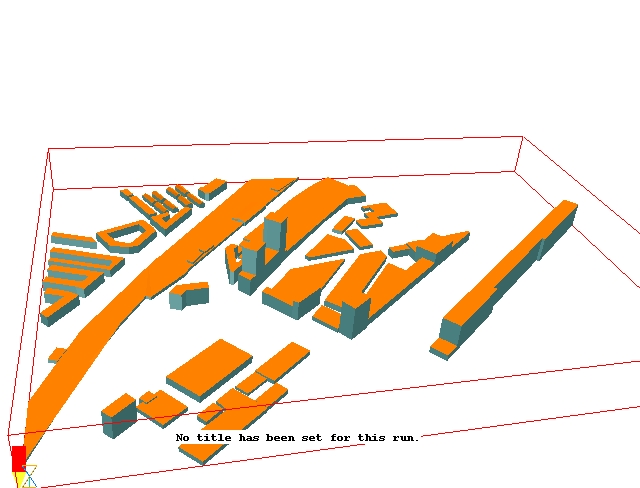
At first sight, viewed from above, this geometry looks acceptable:
In fact, it will not work because none of the buildings have bottoms, so they are not closed volumes. This can be seen when viewed from below.
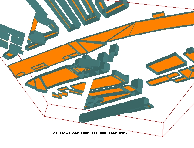
The solver will not detect anything!
Installations of PHOENICS created after May 2013 can utilise the Simlab Composer package from Simulation Lab Software Inc - www.simlab-soft.com.
PHOENICS checks if the Simlab Composer is activated and, if available, then uses this utility to convert any files falling outside of the standard list (shown above.) It does this, without the need for user interaction, first into 3DS format and then to the default .DAT format needed by PHOENICS.
The Simlab Composer can be obtained from CHAM. All that is needed is a request to be made to CHAM, which holds a number of Simlab licence strings.
The Simlab Composer can be used in two different ways: 'passive' or 'active'. DatMaker uses Simlab in passive mode for the direct conversion of 3D CAD files into the PHOENICS .DAT geometry format without user interaction.
All the file extensions listed can be converted automatically in this way.
When used in active mode, the user accesses Simlab via the PHOENICS - VR Utilities menu. Simlab can also be used, for example, to create 3D PDF files for emailing results or geometry to customers.
These third-party programs from Okino Computer Graphics provide a very powerful suite of conversion utilities. They will translate almost any CAD format into almost any other. One of the available export options is STL, so these programs can be used to convert any CAD file into something useable by PHOENICS. The programs have limited capability to modify or repair the CAD model.
The AC3D program can import geometries in many 3D file formats including POV-Ray, VRML (1 and 2), RenderMan, 3D Studio 3DS, Lightwave, DXF, Alias triangle, Wavefront OBJ, Direct X, Milkshape, MD2, Quake 3 BSP.
It can perform Boolean operations on multiple objects - for example to join two intersecting objects and leave only the surfaces of the joined part. It can export PHOENICS geometry files, which are directly useable by the VR-Editor.
Locating and Loading the CAD File
CAD geometries are attached to objects just as the CHAM-supplied geometries are. They can be attached to new objects, or to existing objects. The CAD file(s) to be imported can be anywhere on the file system.
There are three ways of importing an existing CAD file:
then 'New', then 'Import CAD Object', then proceed as below; or,
Any of these actions will bring up a dialog box, which allows the type of file to be imported to be selected:
In either case, a file browser will appear, with which the file to be imported can be selected:
A selection of example CAD files is supplied in the folders:
\PHOENICS\D_INTFAC\D_CADPHO\D_STL
\PHOENICS\D_INTFAC\D_DXF
In this example, PIPES.STL has been selected. The CAD file can be located anywhere on the system.
Once 'Open' on the file selection dialog has been clicked, a confirmation of the input and output file names will be shown:
If happy to proceed, click OK, and the selected file will be translated using the DatMaker module. The options for DatMaker are as follows:
The last two options are mutually exclusive. In either case the names of the output files will be based on the original CAD file name with _1.dat, _2.dat, ... _n.dat added to the end. In addition, a file with a name ending _0.dat will also be created. This file marks the original orign and extent of the single CAD file. It is used as a place holder to ensure the separate files are imported in the correct locations relative to each other.
Note that the more repair processing is selected, the longer the repair may take.
Fitting the CAD Geometry to the Object
Once the translation is complete, the following dialog box will be shown:
This dialog shows how many points and facets were created, and shows the size and origin read from the CAD file. There are then two choices for the size and position:
Whichever option is chosen, the size and location of the object can be changed as desired later. The domain origin and size will be adjusted if necessary to enclose all objects.
Clicking on 'Reset', 'Fit to Window' on the toolbar will rescale the view to show the entire domain.
If the ' Object constrained by domain' tickbox on the General page is cleared before importing the CAD file or 'Object constrained by domain' is set to No on the dialog, the domain will not be resized if the object becomes bigger than the domain.
The Geometry scaling factor allows the CAD data to be transformed from the CAD units to the units used in PHOENICS-VR. These are normally taken to be meters. Typical scaling factors are:
| CAD-Units | Factor |
| mm | 0.001 |
| cm | 0.01 |
| m | 1.0 |
| inches | 0.0254 |
| feet | 0.3048 |
| yards | 0.9144 |
Note that the units of the CAD origin are always assumed to be meters. If they are not, the correct values must be input otherwise the object may be located incorrectly. When the scale is changed, the Xorg, Yorg and Zorg boxes are updated when 'Apply' is pressed.
Alignment of Axes
It is possible to change the alignment of the CAD and PHOENICS-VR axes. By default, the CAD and PHOENICS-VR axes will be the same. If the CAD geometry was created with, say, the X axis pointing up, but the simulation is to run with Y as up, clicking on the CAD X Y Z align with VR button will cycle the alignments through X Y Z, Y Z X and Z X Y. This will ensure that the dimensions of the object bounding box are set correctly. Further orientation changes within the bounding box can be made by clicking on the Rotate Object Down / Up buttons on the hand-set.
Import by Group
There are again three ways of importing several CAD (or DAT) files at one time. These are:
then 'New', then 'Import CAD Group', then proceed as below; or,
Any of the above options will display the Group CAD/DAT Import dialog.
The names of the CAD files to be imported are selected with a file browser. The list can contain a mixture of supported CAD data types and also DAT files.
The options for 'Group origin in PHOENICS domain' are:
The Geometry scaling factor and CAD X Y Z alignment buttons are as described above for a single CAD file.
The type and attributes of the first object are copied to all the remaining objects in the list during the importation process. If the objects share many attributes, it is easier to set these for the first object before importing the list.
An alternative is to import each object in the assembly in turn using the 'Take size from geometry file' and 'Take position from geometry file' options, as described above.
Failure to translate ASCII STL files may be due to the lines ending with Line-feed, rather than Carriage-return+Line-feed. This can be corrected by reading the STL file into WordPad, then saving it. It may be possible to change the output format settings in the CAD system to output a correct file, or to switch to binary format.
Another common error in CAD files is that the normals do not all face outwards. A symptom of this is that the object appears to change shape as the view is rotated, or it appears inside-out. If the setting 'View - Show back of objects' makes the image appear correct, it is a sure sign that some of the normals face in and not out. See the tutorial ' CAD Import / Datmaker: Repairing and Splitting a CAD file into individual objects' for an example.
Although STL formally defines a closed volume, this is not guaranteed. Some STL files may contain holes or gaps between facets. These can lead to detection errors in the Earth solver.
Both types of errors can sometimes be fixed in CAD files using Datmaker, started from Settings - Datmaker operations. The tutorial mentioned above exemplifies the use of Datmaker as part of the process of importing a sequence of STL files.