 GAS-TURBINE COMBUSTION CHAMBER, Library case 492
Encyclopaedia Index
- -
Integer flag; value=9.
R1....standard name used to denote the first-phase volume fraction.
See PHI and NAME for further information.
-----------------------------------------
Integer flag; value=10.
R2....standard name used to denote the second-phase volume fraction.
See PHI and NAME for further information.
-------- PIL real; groups 9 & 13 ---------
RADIA... is used to carry the radiation absorption coefficient in cases where the radiation model is activated.
RADIAT....is a PIL command which is used to activate either the composite-flux radiation model or the composite radiosity radiation model. These radiation models are coded in subroutine GXRADI, which is called from GREX3.
The syntax is:
RADIAT(Model,ABSORB,SCAT,Energy)
where:
The user is advised to employ absolute temperature in degrees K, although the of the PIL variable TEMP0 to define a reference temperature, eg TEMP0=273K is allowed.
The command:
RADIAT(Model,ABSORB,SCAT,Energy)
is equivalent to the following PIL settings:
SOLVE(Energy)
where Energy=H1 or TEM1
IF(NZ.GT.1.AND..NOT.PARAB) THEN
SOLUTN(Energy,Y,Y,Y,P,P,P)
ENDIF
IF(NZ.GT.1.AND..NOT.PARAB)
THEN
SOLUTN(SRAD,Y,Y,Y,P,P,P)
ENDIF
TERMS(SRAD,N,N,Y,N,Y,N)
PRANDTL(SRAD)=-GRND1;PRT(SRAD)=1.E10
PATCH(RADISO,VOLUME,1,NX,1,NY,1,NZ,1,LSTEP)
COVAL(RADISO,Energy,GRND1,GRND1)
COVAL(RADISO,SRAD,GRND1,GRND1)
RADIA=ABSORB;RADIB=SCAT
The user is reminded that in earlier versions of PHOENICS the syntax of the RADIAT command was:
RADIAT(ABSORB,SCAT,CP)
This activated the composite-flux model; solution of the H1 equation; and
set TMP1=GRND2 and TMP1B=1/CP.
This syntax is still supported in later versions, although TMP1
and TMP1B are no longer set.
Therefore, if H1 is solved the user must select the
enthalpy-temperature option and associated specific heat separately;
or alternatively if
TEM1 is solved, the user must set the specific heat via the PIL variable CP1.
>>> For more detailed documentation see the Encyclopaedia entry 'RADIATIVE HEAT TRANSFER IN PHOENICS'.
The star-name-patch feature has a special effect when the variable appearing in the COVAL statement is TEM1, enabling it to represent radiative or free-convective heat loss to (or gain from) surroundings of different temperature.
The RADIATIVE-TRANSFER CASE is activated by following the * in the patch-name by RAD. Then the source introduced within EARTH, per unit area if an area type is chosen, is:
CO * ((VAL + TEMP0) ** 4 - (TEM1cell + TEMP0) ** 4)
where CO and VAL are the COVAL arguments.
Here TEMP0 is the PIL variable representing the quantity which must be added to the temperature on the prevailing scale to make it an absolute temperature. TEMP0 should be set to 273.0 if the Celsius scale is in use.
If CO is made equal to the Stefan-Boltzmann constant, sigma, (ie 5.6697 E-8 W*m**(-2)*K**(-4) ), times the emissivity of the surface, this creates a source having the magnitude:
emissivity * sigma * ( Tsurr ** 4 - Tsurface ** 4)
where T stands for absolute temperature on the Kelvin scale.
This is appropriate to radiative heat loss to (or gain from) surroundings at fixed temperature.
Core library case 608 illustrates the use of this feature.
The FREE-CONVECTIVE CASE is activated by following the * by a plus or a minus and then an integer. Thus:
PATCH(*+2NFACE,north,.........)
COVAL(*+2NFACE,TEM1,CO,VAL) or
PATCH(*-3EFACE,east,..........)
COVAL(*-3EFACE,TEM1,CO,VAL)
The former causes EARTH to provide a source equal to:
CO * (VAL - TEM1cell) ** 2 per unit north area,
and the latter causes EARTH to provide a source equal to:
CO * (VAL - TEM1cell) ** (1/3) per unit east area,
the sign being the same as that of (VAL - TEM1cell).
-------- PIL real; groups 9 & 13 ---------
RADIB... is used to carry the radiation scattering coefficient in cases where the radiation model is activated.
See the help and encyclopaedia items on RADIAT, and GREX3 and GXRADI for further information.
(see RINNER)
RANDOM....is a PIL command which is used to generate a random number.
Syntax of RANDOM()
The single argument of RANDOM is used as the seed for the random number sequence.
The argument can be any valid PIL variable or the result of an expression. The value will be turned into an integer (using the FORTRAN INT() function) before use.
The algorithm used is a "Prime Modulus M Multiplicative Linear Congruential Generator," a modified version of the random number generator by Park and Miller in "Random Number Generators: Good Ones Are Hard to Find," CACM, October 1988, Vol. 31, No. 10.
RANDOM can also be used as an InForm function to be executed at solver run-time.
(Contour Edit Menu) -------------------------------------- Photon Help ----
Only contours within the specified band will be plotted. The colour scale for shaded and filled contours is determined by the lower and upper limit of the band.
(See also PHENC entries: CHEMKIN, CREK & COMBUSTION)
REACTion-rates are represented in PHOENICS as sources or sinks (ie negative sources) of chemical species. The options provided in the standard GROUND coding are primarily intended for the representation of the diminution of fuel in combustion processes (see COMBUS ); but they can also be used for chemical reactions generally.
The options are provided in subroutine GXCHEMSO (for CHemical SOurces) which is called from group 13 of GREX when the first four characters of a PATCH name are CHSO. For example:
PATCH(CHSO,VOLUME,1,NX,1,NY,1,NZ,1,LSTEP)
would be used when the reaction zone is co-extensive with the domain of integration.
The options listed below are expressed in the form required for the source of the mass fraction of fuel, Mfuel, in the SCRS model of combustion described under the COMBUS entry.
COVAL(CHSO,FUEL,GRND5,0.0) which gives the source per unit volume:
In addition to setting the reaction-rate control parameters CHSOD and CHSOE, the user must set: CHSOB=-1.0/CHSOA;CHSOC=1.0/CHSOA-1.0, where CHSO27 is the stoichiometric mixture fraction.
See comments above regarding the user settings for CHSOB, CHSOC, CHSOD and CHSOE.
where CHSOB is the rate-controlling parameter, and CHSOA is the stoichiometric mixture fraction (see COMBUS).
------ Command; defaults 0.0; group 1 - -
REAL....command to declare up to 100 real PIL variables. For example: REAL(RR1,RR2,RR3,RR4) makes RR1, RR2, RR3 and RR4 recognized as PIL variables.
Any name can be used, up to 6 characters, eg REAL(REYNOS).
Such variables can be set in the usual way (eg. RR1=3.1416);
they are also recognized on the right-hand side of
assignment statements
(eg XULAST=RR1 sets XULAST to the current value of RR1 ie 3.1416 ).
They are recognized in arguments of other argument-setting commands, eg
COVAL(BOUND,P1,RR1,RR2) .
They can be combined by using arithmetic operators of the following types:
* / **
and brackets ( ) .
The operands can be any combination of integer and real numbers, PIL variables, array elements and user-declared variables.
Examples are:
In interactive work, the current set of user-declared real variables, and the values assigned to them, may be displayed by entering the command SEER.
The default provision of up to 100 variables can be enlarged by re-dimensioning in the MAIN program of the SATELLITE. See DIMENS for further information.
--------------------------------------
The following real variables are recognised by PIL:
The following real arrays are recognised by PIL:
| CINT | ENDIT | EX | FIINIT | PHINT | PRNDTL | PRT | RESREF |
| RG | TFRAC | VARMAX | VARMIN | XFRAC | YFRAC | ZFRAC |
The FLAGS entry includes a list of the real flags recognised by PIL.
---- Autoplot Help ----
REC[IPROCAL] [X or Y] {i j}
Data elements i-j will have the reciprocal taken of the X or Y values. SCALE will give a correctly scaled plot.
---- Autoplot Help ----
R[EDRAW] [i] [j]
Clear the screen and redraw data elements i - j only. If i and j are unspecified, the plot will be redrawn exactly as it was. Any items deleted or cleared will not be redrawn.
------------------------------------- Photon Help ----
RE[draw].... is a REPLAY command which clears the screen, and redraws the current frame. If NOCLEAR is in effect, then all the frames comprising the current picture will be redrawn.
See also : REPLAY, SCALE, SHIFT, CLEAR, RESET
(View Menu)------------------------------------- Photon Help ----
[Redraw] clears the screen, and redraws the current picture.
(Replay Menu) ------------------------------------- Photon Help ----
[Redraw] clears the screen, and redraws the current frame. If [NoClear] is in effect, then all the frames comprising the current picture will be redrawn.
(see CFIPA, CFIPB, CFIPC, CFIPD)
(see CFIPS)
(see PRESS0)
(see TR218)
----- PIL real; Default=0.0 -------------
Used in conjunction with LIBREF when running test battery.
------ Command; group 2,3,4,5 -------
REGEXT....Command to set the default extent of all regions in a particular direction. Format: REGEXT(T or X or Y or Z, length) Note that this will reset the extent of ALL regions even if issued after GRDPWR commands.
For time distribution, the default region length is 1 second; for X, Y or Z directions the default region length is 1 meter.
(Vector, Contour, Grid, Stream Menu) ------------------------------------- Photon Help ----
The current plotting region on the plotting plane.
See also: [Plane No.]
------------------------------------- Photon Help ----
The sequential number of the blocked region. The maximum is 10. If you type in any number that is less than the total number of block regions defined as seen near the bottom of the window, the limits of the blocked region will be shown and can be edited.
(see IREGX )
(see IREGY )
(see IREGZ)
(see LSTEP)
(see RESTRT)
(see NREGX)
(see NREGY)
(see REGEXT)
(see NREGZ)
This setting affects the solution procedure by causing the increment of a solved-for variable to be multiplied by 'factor' prior to its addition to the in-store value of that variable.
The factor is usually chosen to lie between 0.0 and 1.0, the lower values having the greater slowing-down effect on the solution.
LINRLX is the default for the volume- fraction equations, for which the factor is 0.4 . Linear under- relaxation is often required for P1 in non-orthogonal grids in which NONORT=T.
Two special cases should be noted:
Instead it multiplies the
continuity errors by 'factor' before they enter the pressure-correction
sequence.
This may be a more effective solution-smoothing sequence than under-relaxing
the pressure correction itself, because it results in reduced
(for 'factor' >1.0) velocity
adjustments.
(see entry for P2 ).
Its effect is to add to the conservation equation for each cell a source equal to:
(latest_phi - next_phi) / DTFALS(phi)
where latest_phi is the current value of the variable being solved for, and next_phi is that which it will take after adjustment.
Here the appearance of DTFALS(phi) in the denominator entails that its influence is greater the smaller is its value.
Its importance as compared with other terms in the balance equation depends upon the size of the simulated space in the manner expressed by the following table.
| term | proportional to | and | ||
| convection | reference_length | ** 2 | * | reference_velocity |
| diffusion | reference_length | ** 1 | * | diffusion_coefficient |
| chemical reaction | reference_length | ** 3 | * | reaction_rate |
| time dependence | reference_length | ** 3 | / | time_step |
| DTFALS | reference_length | ** 3 | / | false_time_step |
It follows that account should always be taken of the size of the domain, and of the order of magnitude of the other quantities appearing in the table, when assigning a value to DTFALS; and, since this is hard to do with confidence, it is better not to use false-time-step relaxaton at all.
PATCH-wise false-time step under-relaxation can be introduced by means of PATCH and COVAL by using SAME as the fourth argument of COVAL.
More properly called 'under-relaxation', this is a technique used for preventing the built-in iterative solution process from 'diverging', i.e. failing to 'home in on' unchanging values as the iterations continue.
It thus assists to procure convergence (q.v.). The most common means of achieving it is by assigning 'value' in the PIL connabd: RELAX(variable name,LINRLX or FALSDT, value). (See RELAX)
See VALIDATION
----- PIL real; default=1.0; group 6 -----
RELXC.... linear relaxation parameter for influencing the solution of the coordinate XC when MAGIC(L) is in use. A value of 1.7 is often found to accelerate the rate of convergence of the solution.
----- PIL real; default=1.0; group 6 -----
RELYC.... linear relaxation parameter for controlling the solution of the coordinate YC when MAGIC(L) is in use.
See RELXC for advice.
----- PIL real; default=1.0; group 6 -----
RELZC.... linear relaxation parameter for controlling the solution of the coordinate ZC when MAGIC(L) is in use.
See RELXC for advice.
(Test Menu) ------------------------------------ Photon Help ----
[Replace] modifies an existing text string with a new one. Pick the text string to be modified first then PHOTON will prompt for the new string. Type the new string in the input window near the bottom of the window.
------------------------------------- Photon Help ----
REP[lay]....is used to display frames from previously created SAVE files. It causes the program to enter 'replay mode', within which only the following REPLAY commands are available :-
| FILE | LIST | DRAW | SENDP | DUMP | REDRAW | SCALE | SHIFT |
| RESET | WHERE | 4VIEW | TEXT | MONOCHROME | CLEAR | NOCLEAR |
Help entries are available for all these commands - type 'command ?' to view the help entry for a given command.
See also : SAVE
------------------------------------- Photon Help ----
[Replay] is used to display frames from previously created SAVE files. It activates the 'replay sub-menu'. Immediately after each drawing, the replay menu is invisible. Pressing any key or a button of the mouse will pop up the menu to the screen.
------- PIL logical; group 19 default = F -
When RESET=T in Q1, the subroutine GXRSET (in the file PHOENICS/d_earth/d_core/gxsettim.htm) is called. This monitors the step-to-step change of a user-selected variable, and adjusts the time step if the change is too small or too big.
The field values of the chosen variable are summed over the whole domain, and then averaged by the number of cells.
If the change-limits are exceeded, the time step is reset, and the time step is repeated.
The control parameters are:
| ISG10 | - index of the variable to be monitored. |
| RSG10 | - minimum acceptable change in average value. |
| RSG11 | - maximum acceptable change in average value. |
| RSG12 | - factor used to adjust time step, usually about 0.9. |
The new time step is estimated from:
IF ( average change <RSG10 or> RSG11 ) THEN Dtnew = Dtold * RSG11 * RSG12 / (abs(average change)) ENDIF
-------------------------------------- Photon Help ----
RE[set].... is a REPLAY command which resets the position and scaling used for plotting frames to the default values, which are full size, origin at 0,0. It also deletes any stored frames and resets the display mode to CLEAR.
See also : REPLAY, SCALE, SHIFT, CLEAR, REDRAW
(Results Menu)-------------------------------------- Photon Help ----
[Reset] resets the position and scaling used for plotting frames to the default values, which are full size, origin at 0,0. It also deletes any stored frame and resets the display mode to CLEAR.
(View Menu)------------------------------------- Photon Help ----
Reset all the view parameters (view direction, UP direction, magnification factor...) to the default.
RESFAC is a PIL variable, defaulted to 0.00001, used by PHOENICS, when the PIL variable SELREF = T (its default value), for determining if the solution has converged. When the absolute sum of residuals divided by the reference residual, RESREF, for each variable falls below RESFAC the calculation will terminate.
Users should be aware that the employment of SELREF=T, with a value of RESFAC which is the same for all variables, is a convenient but crude method of controlling the cut-off point of the solution procedure. To set SELREF = F, and set the individual RESREFs for themselves may be safer, when obtaining a well-converged solution is especially important.
Input-library cases 530 and 531 have been designed to enable the influence of RESFAC to be explored.
See also the PHENC entry for RESREF.
These are imbalances (errors) in the finite-volume equations which are computed during the solution procedure, the aim of which, of course, is to reduce them to an acceptable magnitude.
Their magnitudes can be reported to the user, variable-by-variable, in two ways, namely as:
The global values appear both in the result file, where they are influenced by the setting of ITABL, the last 3 arguments of OUTPUT and in the graphical monitor, if that is activated.
The most convenient means of printing and plotting the field values of residuals (and of "corrections" also) is to make use of the In-Form function RESI (and the function CORR for corrections.) For example, the residual of the temperature equation,TEM1, can be placed in the 3D variable T1R by the command
(STORED of T1R is RESI(TEM1))
Similarly, the corrections for the temperature equation can be placed in the 3D variable T1C by the command
(STORED of T1C is CORR(TEM1))
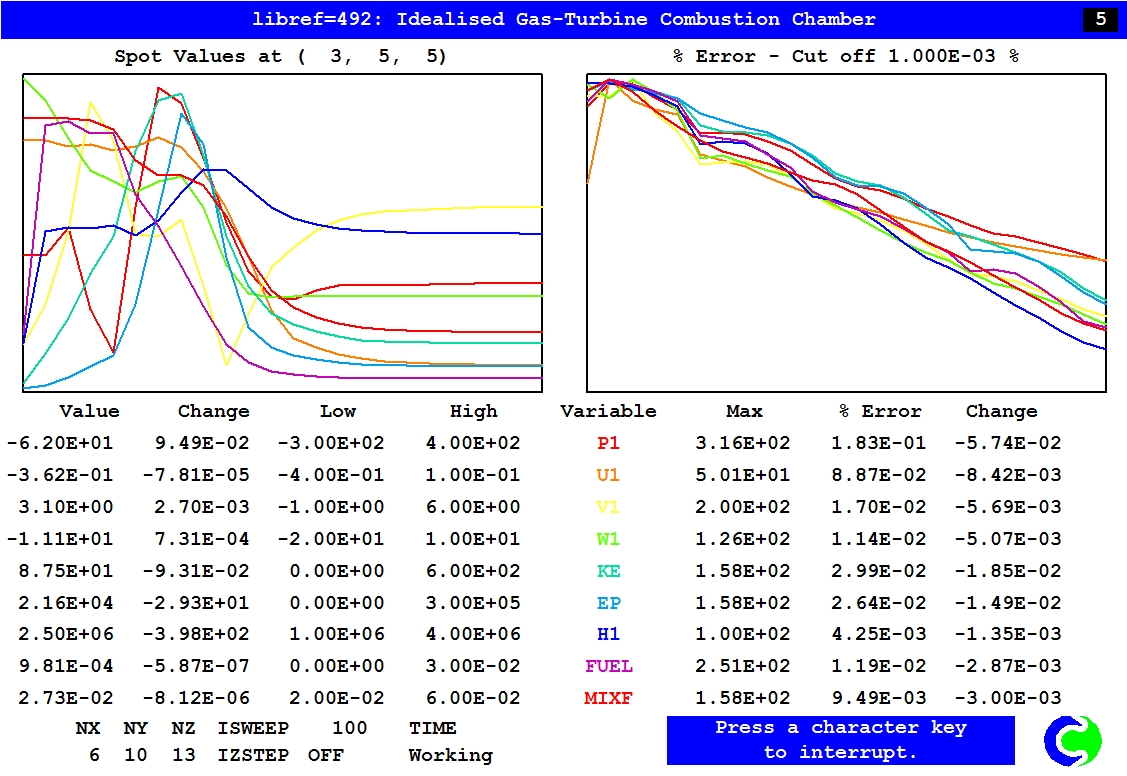
In the RESULT file, the residuals are printed after the flow fields, as in this example from Library case 492:
 Whole-field residuals before solution at sweep 100
 with resref values determined by EARTH
 & resfac=1.0E-05
  variable   resref  (res sum)/resref  (res sum)
     P1     1.837E-01   1.830E-03      3.360E-04
     U1     1.273E+01   8.869E-04      1.129E-02
     V1     1.273E+01   1.701E-04      2.166E-03
     W1     1.273E+01   1.142E-04      1.454E-03
     KE     9.955E+01   2.994E-04      2.981E-02
     EP     1.240E+05   2.641E-04      3.274E+01
     H1     3.852E+05   4.252E-05      1.638E+01
     FUEL   1.146E-03   1.189E-04      1.362E-07
     MIXF   3.515E-03   9.489E-05      3.336E-07
The first column is the normalisation factor (RESREF) for the variable, the second is the normalised residual and the third is the 'bare' or un-normalised absolute sum of residuals. If for example, TEM1 residuals have been STOREd in T1R as above, the following InForm will produce exactly the same value in the INFOROUT file.
(MAKE1 T1ERR is 0.0)
(STORE1 of T1ERR is SUM(ABS(T1R))
(PRINT T1_ERROR is T1ERR)
The run will continue until one of the following conditions is met:
RESREF(variable name) is a PIL array, which may be set in the Q1 file, or by way of the menu.
However, values set there will be effective only if the PIL variable SELREF, the default of which is T, is set to F. Otherwise the values set by the user in Q1 will be over-written in Earth by values calculated as shown below.
RESREF is calculated from:
RESREF = typical flow rate of the variable.
When SELREF=T, it is calculated internally, within the PHOENICS solver module; and its dimensions are: (mass per unit time) * (property per unit mass) .
Thus,
When SELREF=T, the normalisation factor RESREF(φ) for each SOLVEd variable is computed as:
RESREF(phi) = sum of sources + sum of non-directional fluxes + (sum of X-directed fluxes)/(NX-1) + (sum of Y-directed fluxes)/(NY-1) + (sum of Z-directed fluxes)/(NZ-1)
where:
sum of sources - sum of inflows from boundary conditions + sum of interphase sources for two-phase + inflow from old-time for transient

sum of X/Y/Z fluxes - sum of absolute convection flux + sum of absolute diffusion flux
The division by (no cells-1) is because there is no flux stored at the domain edge. The RESREF() values for the momentum equations are set to RESREF(U1)+RESREF(V1)+RESREF(W1) and RESREF(U2)+RESREF(V2)+RESREF(W2) for two phase flows.
When SELREF=T, the solution will terminate when
When SELREF=F, and the sum of the absolute value of the residuals for all variables falls below the associated RESREF, the solution as a whole is terminated.
In these circumstances, it is often suitable to set RESREF(φ) to the sum of the inflow flux of that variable. Sometimes, in order to explicitly prevent early termination, the RESREF is further multiplied by 1.0E12 so that when the displayed residual value is mentally divided by 1.0E10, the outcome is a % error.
In either case, one more sweep of the domain is performed to give print-out, but no solving is done.
GROUND is informed about the termination of iterations and sweeps by the two logical variables ENUFIT and ENUFSW. When the slab-wise iterations ( governed by LITHYD ) terminate, ENUFIT is set to T; when the sweeps are terminated, ENUFSW is set T.
In the RESULT file, the print-out of the whole-domain residual sum for each variable is normalized by its RESREF; therefore printed values below RESFAC signify that the convergence criterion has been satisfied.
The diminution of the residuals during the course of the solution may be observed by way of the graphical monitor, activated by TSTSWP=-1, as shown in the following picture. In the case shown, none of the residuals has fallen to the reference value.
GAS-TURBINE COMBUSTION CHAMBER, Library case 492
---- Command; group 11 --------------
RESTRT(variable name 1,variable name 2,...etc.) is a command which instructs EARTH to read the initial fields of the specified variables from the restart file.
Restart files ( named PHI or PHIDA by default according to the
presence in the PREFIX
file of the lines PHIDA=F or PHIDA=T respectively) are created in runs for which the PIL variable,
SAVE, equals T ( which is the default )
except when given a
different name by the PIL statement:
NSAVE
= four-character file name.
NSAVE names the file to which the fields are dumped at the end of a run; but to instruct EARTH to take its values from that file, the command:
NAMFI = four-character file name
must appear in the Q1 file.
The RESTRT command permits the user to select which of the fields on the restart file he wishes to use as the initial fields of a subsequent calculation. In addition to those fields selected from the restart file, new variables can be introduced for storage and solution on any restart run.
The most common use of RESTRT is to perform "continuation runs" by means of the instruction RESTRT(ALL), which ensures that all variables will be read. FSWEEP may be set to the last sweep of the previous plus one, so as to keep track of the number of sweeps to date.
RESTRT(phi) acts by setting FIINIT(phi) equal to the flag READFI, (signifying "read from a file")
Its effect can be undone by re-setting FIINIT(phi) to any other value.
RESTRT(NONE) will reset all FIINIT values to 1.0E-10.
Special care is needed when restarts are to be made from runs in which the
GCV algorithm is in use for
a multi-block grid.
The reason is that, to permit PHOTON to represent such flows properly, the
dumped is modified; but the modification renders the file unsuitable for
restarting.
The modification is not made however when both nsave and namfi are
both set to the same name, eg 'othr', for this is taken by EARTH as a signal
that a restart is intended.
See FIINIT for further information.
-----------
(also referred to as RSTM)
See PHOENICS encyclopaedia file, Turbulence Models in PHOENICS: Reynolds-stress turbulence model
RG array This array of real variables can be set in SATELLITE and is recognised by GX-type subroutines if the appropriate COMMON is included. When it was first introduced, RG was intended to be kept available for users who were writing their own GROUND subroutines. However, its use has spilled over into subroutines made available to ALL users. Therefore, in preparation for the launch of version 2, this excessive use was curbed in accordance with the rules:-
Similar remarks apply to the arrays IG( ), LG( ) and CG( ).
RG2D is an integer index, usable in subroutines called from GROUND, for accessing the 2D array of values, pertaining to the current IZ-slab, of:
distances from the axis of symmetry to the cell centres. RG2D is of significance only in cylindrical-polar coordinates, i.e. when CARTES=F and BFC=F.
----- PIL real flag; value= 14.0; group 13 -
RGRAD....is a PATCH type, to provide by means of COVAL momentum sources of magnitude equal to:
(cross-sectional area in direction of velocity)*0.5*
(sum of phase volume fractions on either side of velocity node)
*(decrement of volume fraction in the velocity direction)
*(the quantity appearing in the "value" argument of COVAL) .
Momentum sources of this kind occur when shallow layers of fluid are influenced by gravity. Then the "value" is the fluid density times the gravitational acceleration, times the vertical height of the channel cross-section.
The first three terms in the above expression represent the proportion of the cross-sectional area over which the associated pressure difference operates; and it is valid only for wide or rectangular-sectioned channels.
If the cross-section is not rectangular, the RGRAD option should not be used. Subroutine GXLATG ( for lateral gravity ) called from GREX provides the option valid for a pipe of circular cross-section. It makes use of the functions FN101, FN102 and FN103. See the GRAVity entry for further information.
The third (coefficient) argument of COVAL has no significance for RGRAD-type PATCHes, and is best set to zero.
------ PIL variable; Real; default= 1.0; group 9
RHO1 signifies the density of the first phase.
Contents
If RHO1 is given a positive value, that value is used for the first-phase density by EARTH.
Recourse to GROUND is necessary when the density is a function of other variables. The following options have been provided in subroutine GXDENS called from within EARTH; they are selected as indicated below:- RHO1 = GRND1
RHO1=GRND1 selects one of the following:
or
or
or
RHO1=GRND2 selects: density=1./(RHO1A+RHO1B*h1) .
RHO1=GRND3 selects: density=RHO1A*(p1+PRESS0)**RHO1B+RHO1C, where p1 is the relative pressure stored in P1. This option is the one to use for isentropic gas flow.
RHO1=GRND4 selects: density=RHO1A+RHO1B*t1, where t1 is the first phase temperature stored in T1 ( see also TMP1 ).
RHO1=GRND5 selects one of the following:
This option is the one to use for ideal-gas flow with constant gas constant, 1/RHO1B
or
This option is the one to use for ideal-gas flow with species- dependent gas constant.
Here:
In both cases p1 is the relative pressure stored in P1 and t1 is the first phase temperature stored in T1 determined by the ascription of TMP1, or TEM1, depending on whether H1 or TEM1 is solved.
RHO1=GRND6 is for use with the simple chemical reaction scheme of combustion ( see COMBUS ).
This option sets,
density=
(p1+PRESS0)*Wmix/(8314.3*t1), where:
the mixture molecular weight is computed from:
RHO1 = GRND7 Setting rho1 to GRND7 activates the seven-gases options, which is often used for the simulation of hydrocarbon-air combustion.
RHO1 = GRND8 Setting rho1 to GRND8 activates the density options of the special-purpose program PHOENICS-CVD if this forms part of the installation.
RHO1 = GRND9 Setting rho1 to GRND9 activates the density options of the CHEMKIN add-on.
RHO1 = GRND10 Setting rho1 to GRND10 sets density as the reciprocal of a linear function of temperature.
If these options failed to meet the user's needs, in the past, he or she would have had to set RHO1=GRND and to provide Fortran coding in subroutine GROUND, in GROUP 9 SECTION 1.
Nowadays however it is preferable to use either the In-Form feature, or PLANT.
See the PHENC entry for GROUND for examples of this.
For the density formulae which imply a strong pressure dependence, the variable DRH1DP should be set accordingly. DRH1DP is set automatically in options GRND3 and GRND5.
----- PIL real; default= 0.0; group 9, se -
RHO1A....parameter used in phase-1 density formulae. Further parameters of the same kind are: RHO1B,RHO1C.
------ PIL real; default= 0.0; group 9, se -
RHO2....density of the second phase, used similarly to RHO1.
See RHO1 for further information.
The following feature is useful when shallow-water theory is extended to the simulation of
waves on deep water:
RHO2 is used to convey what the reference density is; but it is given
a negative sign so as to signal that this is its ( unusual ) role.
----- PIL real; default= 0.0; group 9, se -
RHO2A....parameter used in phase-2 density formulae. Further parameters of the same kind are: RHO2B,RHO2C.
---------------- R Photon Help ----
[Right/LeftHand System] changes the coordinate system to a left-handed or a right-handed coordinate system. The default is [RightHand System].
---- PIL real; default= 0.0; group 4 --- -
RINNER....Inner radius, i.e. the distance from the axis of symmetry to the cylinder y=0. The default setting of zero therefore corresponds to the straightforward cylindrical-polar coordinate system in which y is measured from the axis of symmetry.
RINNER can be set greater than zero, for example to specify the flow through an annulus, or for the calculation of flow over of a body of revolution whose shape, in parabolic flows, may be distorted by SNALFA.
---- PIL real; default=0.0; group 8 -----
RLOLIM....For DONACC=T, set to the value of the volume fraction of phase 1 below which cell will be regarded as being empty of this phase.
RLOLIM can also be used to prevent interphase friction from vanishing when the volume fraction is zero: see CFIPS for details.
------------ PIL real; default=1.0
RLXU1... is underrelaxation factor for U1
------------ PIL real; default=1.0
RLXV1... is underrelaxation factor for V1
------------ PIL real; default=1.0
RLXW1... is underrelaxation factor for W1
See PHENC entry: RNG-derived KE-EP turbulence model
---------- PIL real; group 13 -----------
ROTAXA... is used in GXROTA for BFC cases with rotating coordinate systems to specify the x-value of one of a pair of points that define the axis around which the rotation occurs. See the help and PHENC items on ROTA, and GXROTA for further information.
---------- PIL real; group 13 -----------
ROTAXB... is used in GXROTA for BFC cases with rotating coordinate systems to specify the x-value of one of a pair of points that define the axis around which the rotation occurs. See the help and PHENC items on ROTA, and GXROTA for further information.
-------- PIL real; group 13 -----------
ROTAYA... is used in GXROTA for BFC cases with rotating coordinate systems to specify the y-value of one of a pair of points that define the axis around which the rotation occurs. See the help and PHENC items on ROTA, and GXROTA for further information.
-------- PIL real; group 13 -----------
ROTAYB... is used in GXROTA for BFC cases with rotating coordinate systems to specify the y-value of one of a pair of points that define the axis around which the rotation occurs. See the help and PHENC items on ROTA, and GXROTA for further information.
-------- PIL real; group 13 -----------
ROTAZA... is used in GXROTA for BFC cases with rotating coordinate systems to specify the z-value of one of a pair of points that define the axis around which the rotation occurs. See the help and PHENC items on ROTA, and GXROTA for further information.
-------- PIL real; group 13 -----------
ROTAZB... is used in GXROTA for BFC cases with rotating coordinate systems to specify the z-value of one of a pair of points that define the axis around which the rotation occurs. See the help and PHENC items on ROTA, and GXROTA for further information.
A ROTOR object is used to define a region of rotating coordinates with a static cylindrical-polar grid. See the description in the PHOENICS_VR Reference Guide, TR326
(see NROWCO)
-----------------------------------------
Integer flag; value=11.
RS....standard name used to denote the second-phase shadow volume fraction, i.e. that
which would be present in the absence of inter-phase mass-transfer. RS is especially
useful for the simulation of particle combustion.
See PHI ,
NAME and
prtsiz for further information.
---- PIL logical; default= F; group 6 --- -
RSTGEO....may be set to T to initiate a BFC geometry restart. When done this ensures that all the geometrical quantities required for BFC working are read from the pre-existing file, which must have been created in an earlier run by setting SAVGEO to T. Normally, when RSTGEO is set T, SAVGEO should be set F for there is no need to save the geometry on each run, especially as the act of so doing may be time-consuming. Note that on some systems the time taken to read the file may be greater than the cpu time taken to re-calculate all the geometrical quantities.
------ PIL logical; default=F; group 19 --- - < 95:13>
Set RSTM=T to activate the Reynolds-stress turbulence-model.
See Reynolds-stress Turbulence Model
A grid made up of dashed lines parallel to the axes, at intervals corresponding to the axis calibrations, may be ruled on the plot by the command GRID. A second GRID command will remove the grid again, and further repetitions of the command will alternately restore it and remove it.
You can obtain more closely-spaced grids by using the command GRID DEFINE, which enables you to specify the intervals you require.
For logarithmically-scaled axes, the GRID command will draw a ruled grid at the powers of ten. To rule a finer grid based on the subsidiary calibrations, you should use the GRID DEFINE command. As usual, this will request grid spacings in the x-and y-directions. In a direction plotted logarithmically, you must enter a number for the grid spacing, although it will not be used. In a direction plotted linearly, the number you enter will be used for the grid spacing (as is always the case for linear plots).
This PIL command is the second item (after TALK) on the first line of
the Q1 file. This line often appears thus:
TALK=T; RUN(1,1),
where the arguments 1,1 signify that only the first run appearing in Q1 is
to be read by the
SATELLITE, i.e. all the PIL statements following this line up to the first STOP
will be read.
When the Q1 contains more than one STOP, with a distinct set of PIL statements between each, RUN can be used to select which set (or sets) is (or are) to be used.
Thus, RUN(10,20) would cause the SATELLITE to read the 11 sets of statements following the 9th STOP up to the 20th STOP.
RUN can also be used to select individual sets in the range indicated Thus, RUN(10,20:12,15,19) would cause runs 12, 15 and 19 to be read.
(GROUP 1)
Command-line entry which starts the execution of AUTOPLOT on any system.
Command-line entry which starts the execution of the Windows/Intel or Unix/Linux version of the PHOENICS flow-solver module, EARTH.
(see TR218)
Command-line entry which starts the execution of the Windows/Intel or Unix/Linux version of the PHOENICS graphical-display module, PHOTON)
(A command to run PINTO)
(A command to run PHOTON)
This command causes the Windows/Intel PHOENICS-Input module (SATELLITE) to begin execution
---- PIL real; default= 0.0; group 8 --- -
RUPLIM....For DONACC=T, set to value of R1 (volume fraction of phase 1) above which cell will be regarded as being full of this phase.
RV2D is an integer index, usable in subroutines called from GROUND, for accessing the
2D array of values, pertaining to the current IZ-slab, of:
distances from the axis of symmetry to the north wall of the continuity cells, at which
the v velocities are stored.
RV2D is of significance only in cylindrical-polar coordinates, i.e. when CARTES=F and
BFC=F.
Note that this index is present only if CALL MAKE(RV2D) is present in Group 1, Section 1 of GROUND.
wbs